Проект Situational Awareness -> Situational Awareness Library
Meters
Meters (вимірювачі) забезпечують графічне та числове відображення показань приладу. Графічне представлення дозволяє візуально порівнювати PV з контрольними значеннями, такими як межі тривоги та/або налаштовані користувачем опорні значення (наприклад, «трекер» або оптимальний діапазон). Багато вимірювачів мають варіації, які дозволяють також використовувати їх для представлення регулятору. Ці варіації включають додаткові елементи, такі як вихід (OP) та індикатор зворотного зв’язку (FB).
Ви можете вставити кілька екземплярів вимірювача в двох або трьох примірниках за допомогою MeterMultiple.xml Composite Genie.
Вимірювачі пов’язані з обладнанням і вимагають визначення таких елементів:
| Item Name | Description |
|---|---|
| FB | Feedback Indicator |
| OP | Output |
| ORDsp | Optimal Range Display |
| ORLow | Optimal Range (OR) Low |
| ORHigh | Optimal Range (OR) High |
| PR | Practical Range specific to Deviation meters |
| PRLow | Practical Range (PR) Low |
| PRHigh | Practical Range (PR) High |
| PV | Process Variable |
| PVTarget | Process Variable specific to Target meters |
| PVTrack | Process ValueTracker |
| SP | Setpoint |
| TrackDsp | Controls whether or not a tracker is displayed |
Об’єкти вимірювача, доступні в бібліотеці Situational Awareness, включають:
Meter Orientations
Для більшості вимірювачів передбачено кілька орієнтацій, щоб надати розробникам сторінок гнучкість у тому, як викладена графіка.
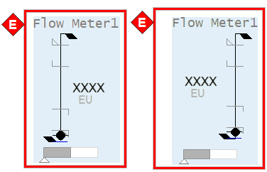
Mirrored
Дзеркальний вимірювач змінює положення ліворуч і праворуч деяких елементів вимірювача, як показано в прикладі нижче. Впливають на положення індикатора робочого стану, стрілки швидкості зміни, PV, інженерних одиниць та індикатора режиму (для control meters).
Horizontal
Орієнтація вимірювача змінюється на горизонтальну, як показано в прикладі нижче. Зверніть увагу, що пропорції межі тривоги, символу вимірювача та індикатора виходу регулятору дещо відрізняються для горизонтальної версії порівняно з вертикальною.
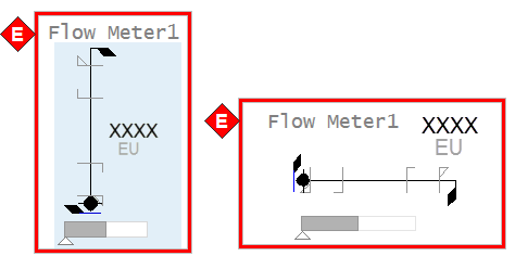
Horizontal + Mirrored
Горизонтальні лічильники також можуть бути дзеркальними. Як правило, ця орієнтація використовується переважно зі звичайними лічильниками, а не контрольними.

Meter Common Elements
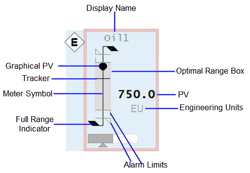
На малюнку нижче показаний приклад елементів, з яких складається метр.
Meter Symbol and Graphical PV
Графічний PV підключається до: EquipmentName.PV, EquipmentName.PVTarget
Зовнішній вигляд символу вимірювача та графічного PV повідомляє операторам, який тип показань відображається (потік проти температури та тиску тощо). Наприклад, витратоміри представлені як базова форма «палиці» з чорною крапкою як графічний PV. Температури нагадують термометр. Рівнеміри нагадують (тонку) посудину з заливкою, яка піднімається і опускається, щоб відобразити рівень, і так далі. Символи та PV для кожного типу лічильників показано на наступному зображенні.
| Analyzer Meter | Deviation Meter | Flow Meter | Level Meter | Misc Meter | Pressure Meter | Target Meter | Temperature Meter |
|---|---|---|---|---|---|---|---|
 |
 |
 |
 |
 |
 |
 |
 |
Full Range Indicators
Підключається до: EquipmentName.PRHigh, EquipmentName.PRLow, EquipmentName.PR
Кожен вимірювач дозволяє встановити «нормальний» робочий діапазон («практичний» діапазон). Під час більшості робочих ситуацій повний діапазон вимірювача набагато більше, ніж фактична область інтересу. Встановивши нормальний робочий діапазон, ви можете побачити значущі зміни в PV, дивлячись на вимірювач.
Пункт EquipmentName.PR застосовний лише до вимірювачів відхилень. PRHigh і PRLow не застосовуються до цих вимірювачів.
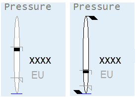
Якщо PV виходить за межі нормального робочого діапазону, шкала вимірювача автоматично зміниться, щоб відобразити весь діапазон приладу. Щоб розрізнити вимірювач, який показує весь діапазон, у верхній частині лічильника з’являються додаткові прапорці, а колір лінії символу лічильника змінюється з сірого на чорний, як у прикладі нижче:
Alarm Limits
Підключається до: EquipmentName.PV (analog alarm - current) або (EquipmentName.HHAlm, EquipmentName.HAlm, EquipmentName.LAlm, EquipmentName.LLAlm) або PLC Alarm Limits if configured.
На символі вимірювача з’являються індикатори ліміту тривоги, щоб показати розташування будь-яких налаштованих меж тривоги. Це дозволяє операторам бачити, коли PV наближається до межі тривоги. Чотири типи меж тривоги відображаються різними символами.
Note: Додаткову інформацію про налаштування лімітів тривоги ПЛК див Associate PLC Limits with Equipment.
 |
High high alarm limit |
 |
High alarm limit |
 |
Low alarm limit |
 |
Low Low alarm limit |
Детальніше, див Alarm Indicators.
Індикатор ліміту тривоги не з’явиться, якщо відповідне обмеження тривоги не налаштовано для приладу або якщо межа виходить за межі діапазону, показаного вимірвювачем. Зауважте, що точна ширина індикаторів ліміту тривоги дещо відрізняється для різних типів вимірювачів, щоб врахувати ширину символу вимірювача. Наприклад, індикатори ліміту тривоги ширші на рівнемірі, ніж на витратомірі.
Engineering Units
Підключається до: EquipmentName.PV (eng units field).
Інженерні одиниці представляють одиницю вимірювання для приладу.
PV
Connects to: EquipmentName.PV, EquipmentName.PVTarget
Числовий PV забезпечує текстове представлення показань приладу. Це надає операторам точні значення, коли це необхідно.
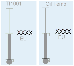
Відображувальне значення/Nickname
Відображуване ім’я/псевдонім показує назву інструменту (за замовчуванням) або, якщо введено користувачем, «відображаючу назву». Псевдонім зазвичай використовується, щоб допомогти ідентифікувати показання (наприклад, «Температура масла» замість «TI1001»). Поле вміщує до 79 символів.
Optimal Range Box
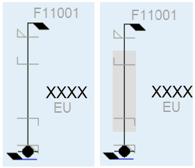
Connects to: EquipmentName.ORHigh, EquipmentName.ORLow, Visibility connected to EquipmentName.ORDsp.
Оптимальний діапазон виділяє певний діапазон вимірювача. Як правило, оператори використовують цю функцію, щоб нагадати собі про бажаний або «оптимальний» діапазон для PV, залежно від умов експлуатації. Повинна бути можливість увімкнути та встановити кінцеві точки для оптимального діапазону від деталей точки. Якщо оптимальний діапазон не встановлено або не ввімкнено, поле не відображається.
Tracker
Connects to: EquipmentName.PVTrack, EquipmentName.OPTrack, EquipmentName.TrackDsp.
Подібно до коробки оптимального діапазону, трекер є налаштованим користувачем індикатором, який позначає конкретне значення на вимірювачі. Оператор може позначити поточне значення PV, щоб, коли вони пізніше знову переглянуть показання, вони могли побачити, чи змінилося воно. Трекер можна налаштувати та ввімкнути/вимкнути з передньої панелі вимірювача.
![]()
Керівні вимірювачі (Control Meters) - Common Elements
Коли вимірювач використовується для показу показань з регулятору, включається додаткова інформація. Керівні вимірювачі включають усі загальні елементи, описані раніше для звичайних вимірювачів, а також додаткові елементи, показані нижче.
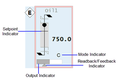
Setpoint Indicator
Connects to: EquipmentName.SP
Індикатор уставки — це додаткова позначка на символі вимірювача (подібна до індикаторів трекера та ліміту тривоги), яка показує положення заданого значення регулятору.
Output Indicator
Connects to: EquipmentName.OP
Форма зовнішнього прямокутника з білою заливкою представляє весь діапазон виводу регулятору ( зазвичай 0-100%), тоді як темніша заливка представляє вихідне значення.
Feedback Indicator
Connects to: EquipmentName.FB
Цей невеликий трикутний індикатор представляє фактичний вихід для регулятору (якщо доступний з системи керування). Він має ту саму шкалу, що і індикатор виходу регулятору (наприклад, 0-100%). Це дозволяє оператору швидко побачити, чи збігаються вихідні та фактичні вихідні значення. Це може бути особливо корисно, коли регулятор має функцію наростання.
Mode Indicator
Connects to: EquipmentName.CtrlMode, EquipmentName.CtrlModeDef
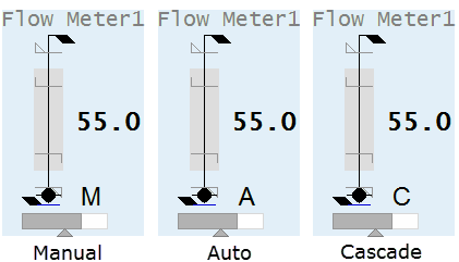
Це односимвольний код, який вказує на режим роботи регулятору. Як правило, набір режимів включає ручний (M), автоматичний (A) і каскадний (C).
Control Mode Indicator states:
- 0 – Auto (A)
- 1 – Manual (M)
- 2 – Cascade (C)
- 3 – Local (L)
- 4 – Special control (computer symbol)
Примітка: Індикатор режиму не відображається, якщо для тега встановлено значення CtrlModeDef. Щоб постійно переглядати режим керування, видаліть тег CtrlModeDef із шаблону обладнання.
Meter Special Elements
Деякі вимірювачі можуть мати елементи на додаток до описаних у Загальні елементи вимірювача. Є три спеціальні елементи.
Differential Indicator
Символ дельта (Δ) використовується для вимірювачів температури та тиску, щоб вказати, коли відображаються диференціальні показання. Це статичний елемент, який включається при конфігурації і не підключається до системи керування. Він складається з простого трикутника, який розміщений поруч із лічильником.
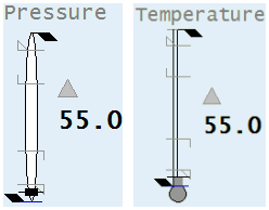
Descriptor
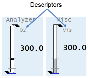
The Miscellaneous, Deviation, and Analyzer meters can all be used to show many different types of readings. Therefore, it is recommended that short text (up to 3 characters) is provided to help identify the reading (e.g., “O2” for Oxygen content, “SG” for density, “Vis” for viscosity, “Trq” for torque, etc.) .
Вимірники Miscellaneous, Deviation та Analyzer можуть використовуватися для відображення різних типів показань. Тому рекомендується надавати короткий текст (до 3 символів), щоб допомогти визначити показання (наприклад, “O2” для вмісту кисню, “SG” для густини, «Vis» для в’язкості, «Trq» для крутного моменту тощо .) .
Clock Timer
Connects to: EquipmentName.Timer, EquipmentName.TimerEXP
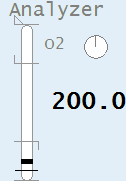
Таймер годинника є незалежним об’єктом, який інтегрований з вимірювальними приладами Analyzer. Його можна використовувати в тих випадках, коли аналізатор показує переривчасті показання зразка. Для цих типів показань таймер годинника показує, як давно значення було оновлено. Це допомагає операторам зрозуміти, наскільки поточне значення. Якщо аналізатор зчитує безперервно, таймер годинника не відображається.
Analyzer Meter
| Property | Description |
|---|---|
| Name | Analyzer |
| Graphical Representation | 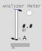 |
| Example Equipment Template | Meter |
| Associated Composite Genie | Meter.xml |
| Equipment.Items that the Genie expects | OPORHigh, ORLow, ORDspPRHigh, PRLowPVTrackPVSPFBCtrlMode, CtrlModeDefRunStatusEqStatusTrackDspTimer, TimerExp |
| Equipment Parameters the Equipment Items Expect | InternalIODeviceCicodeIODeviceEqStatusFuncCtrlModeRangeAlarm Limits |
| Associated Faceplate(s) | Analog ControllerAnalog Indicator |
| Equipment.Items that the Faceplate Expects | OPORHigh, ORLow, ORDspPRHigh, PRLowOPTrack, PVTrack, TrackDspPVSPCtrlMode, CtrlModeDefAutoCmd, ManCmd, CasCmd RunStatusOOS, OOSDisabled |
Configuration Tasks
- Create equipment and organize equipment in a hierarchy: Create equipment instances for the required objects, and organize the equipment in a hierarchy. Objects can be referred to by their name when you add Composite Genies to a graphics page. You can add one or more instances of an equipment to a page.
- Associate PLC Alarm Limits for Meters: This is an optional task that is required if you want to use PLC alarm limits instead of the standard analog alarm limits.
- Insert a Composite Genie: Create graphics pages with instances of Composite Genies that are associated with the equipment you have defined in your project.
- Create a new faceplate: Add a faceplate for the equipment to allow operators to engage with the equipment at runtime.
- Write Cicode functions to initialize PR and OR values. Refer to the Cicode Reference Online help for more information. It is recommended that for a Dual Level meter you set these values on both meters to the same value.
Presentation Options
The following presentation options are available for this object.
| Option | Description |
|---|---|
| Meter Type | From the drop-down select one of the following meters: Level, Flow, Temperature, Pressure, Analyzer, Miscellaneous, Target, Deviation and Dual Level |
| Equipment Name | Enter a name for the equipment associated with the meter. You can enter a maximum of 160 characters for this option. |
| Equipment Item Prefix | Prefix applied to the equipment item name. This allows for displaying multiple values for a single piece of equipment. For example, you want to create three meters to monitor power, voltage and current for a single pump. You would create three meters on the pump and assign the equipment item prefix “Power”, “Voltage” and “Current”. So, the PV values for the meters would be PowerPV, VoltagePV and CurrentPV respectively.Note: To get a meter with a prefix to work correctly, you need to create tags with the required item names. From the example above, you will need to create the tags PowerPV, PowerOP, VoltagePV, VoltageOP, CurrentPV, CurrentOP and so on.The following equipment item names (where applicable) can be prefixed: FB FullScale OP ORDsp ORLow ORHigh PRLow PRHigh PV PVTrack PVTarget SP Timer TrackDsp |
| Size | Size of the meter object image - small or large |
| Orientation | Select the orientation that is appropriate for the presentation of the object on the graphics page. |
| Display Label | Use this setting to display a label at the selected position. Select None if you do not want to display a label. |
| Label | Enter the text that will display at the location specified in Display Label field. You can enter a maximum of 30 characters for this option. |
| Display Alarm Indicator | Select this option to display an alarm border around the Genie. |
| Display Alarm Flag | Use this setting to display an alarm flag at the selected position. Note: If you select the same position for the alarm flag and Display Status indicator (see below), they will overlap. The alarm flag will not be visible. |
| Display Status Indicator | Use this setting to display a status indicator at the selected location. Select None if you do not want to display the status indicator. For more information, see Status Indicators. |
| Display Process Variable | Select to display a process variable (numeric PV) with the meter. This option is selected by default. |
| Display Control Mode | Select this option to display the Controller Mode Indicator. On selecting this option the Display Control Readback option box is also displayed. The Display Control Readback Indicator represents the actual output for the controller. |
| Display Controller Output | Select to display an output indicator with the meter. For more information, see Output Bar. |
| Display Setpoint | Select to display a setpoint indicator with the meter. |
| Display OOS | Select to display Out of Service indicator. |
| Display Differential Indication | Select to display an indicator when a differential reading is detected. This is visible only on Pressure and Temperature meters. For more information, see Meter Special Elements. |
| Descriptor | Enter a short 3-character text descriptor to indicate what is being measured. If left blank no descriptor will be displayed. This is visible only on Miscellaneous, Deviation and Analyzer meters. |
| Display Clock Timer | Select to display a clock timer on the meter. This is visible only on Analyzer meters. For more information, see Meter Special Elements. |
| Display Control Readback | Select to display a readback indicator (also known as feedback indicator) with the meter. |
| Display Trend | Select this option to display a Trend object with the meter. On selecting this option, the Trend Type dropdown is displayed. Select either Tail or Full.Note: When the Display Trend option is selected, the Mirrored option is not available. |
| Trend Type | Select the type of trend to be displayed with the meter: Tail or Full. |
| Mirrored | Inserts a mirror image of the meter based on the selected presentation options. |
Deviation Meter
The deviation meter is used to represent the difference between two values. A positive difference is shown as a bar extending upwards from the middle of the meter symbol. A negative difference extends downwards. The configured input range for the deviation meter needs to be in equal proportions around a zero (for example -200 to +200 or -50 to +50). The PV will be shown as a deviation from setpoint, where zero=setpoint. If the PV exceeds this range, the color of the bar will change to black.
| Property | Description |
|---|---|
| Name | Deviation |
| Graphical Representation | 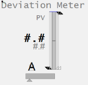 |
| Example Equipment Template | DeviationMeter |
| Associated Composite Genie | Meter.xml |
| Equipment.Items that the Genie expects | OPORHigh, ORLow, ORDspPRPVTrackPVSPFBCtrlMode, CtrlModeDefRunStatusEqStatusTrackDsp |
| Equipment Parameters the Equipment Items Expect | InternalIODeviceCicodeIODeviceEqStatusFuncCtrlModeRangeAlarm Limits |
| Associated Faceplate(s) | Analog ControllerAnalog Indicator |
| Equipment.Items that the Faceplate Expects | OPORHigh, ORLow, ORDspPRHigh, PRLowOPTrack, PVTrack, TrackDspPVSPCtrlMode, CtrlModeDefAutoCmd, ManCmd, CasCmd RunStatusOOS, OOSDisabled |
Configuration Tasks
- Create equipment and organize equipment in a hierarchy: Create equipment instances for the required objects, and organize the equipment in a hierarchy. Objects can be referred to by their name when you add Composite Genies to a graphics page. You can add one or more instances of an equipment to a page.
- Associate PLC Alarm Limits for Meters: This is an optional task that is required if you want to use PLC alarm limits instead of the standard analog alarm limits.
- Insert a Composite Genie: Create graphics pages with instances of Composite Genies that are associated with the equipment you have defined in your project.
- Create a new faceplate: Add a faceplate for the equipment to allow operators to engage with the equipment at runtime.
- Write Cicode functions to initialize PR and OR values. Refer to the Cicode Reference Online help for more information. It is recommended that for a Dual Level meter you set these values on both meters to the same value.
Presentation Options
The following presentation options are available for this object.
| Option | Description |
|---|---|
| Meter Type | From the drop-down select one of the following meters: Level, Flow, Temperature, Pressure, Analyzer, Miscellaneous, Target, Deviation and Dual Level |
| Equipment Name | Enter a name for the equipment associated with the meter. You can enter a maximum of 160 characters for this option. |
| Equipment Item Prefix | Prefix applied to the equipment item name. This allows for displaying multiple values for a single piece of equipment. For example, you want to create three meters to monitor power, voltage and current for a single pump. You would create three meters on the pump and assign the equipment item prefix “Power”, “Voltage” and “Current”. So, the PV values for the meters would be PowerPV, VoltagePV and CurrentPV respectively.Note: To get a meter with a prefix to work correctly, you need to create tags with the required item names. From the example above, you will need to create the tags PowerPV, PowerOP, VoltagePV, VoltageOP, CurrentPV, CurrentOP and so on.The following equipment item names (where applicable) can be prefixed: FB FullScale OP ORDsp ORLow ORHigh PRLow PRHigh PV PVTrack PVTarget SP Timer TrackDsp |
| Size | Size of the meter object image - small or large |
| Orientation | Select the orientation that is appropriate for the presentation of the object on the graphics page. |
| Display Label | Use this setting to display a label at the selected position. Select None if you do not want to display a label. |
| Label | Enter the text that will display at the location specified in Display Label field. You can enter a maximum of 30 characters for this option. |
| Display Alarm Indicator | Select this option to display an alarm border around the Genie. |
| Display Alarm Flag | Use this setting to display an alarm flag at the selected position. Note: If you select the same position for the alarm flag and Display Status indicator (see below), they will overlap. The alarm flag will not be visible. |
| Display Status Indicator | Use this setting to display a status indicator at the selected location. Select None if you do not want to display the status indicator. For more information, see Status Indicators. |
| Display Process Variable | Select to display a process variable (numeric PV) with the meter. This option is selected by default. |
| Display Control Mode | Select this option to display the Controller Mode Indicator. On selecting this option the Display Control Readback option box is also displayed. The Display Control Readback Indicator represents the actual output for the controller. |
| Display Controller Output | Select to display an output indicator with the meter. For more information, see Output Bar. |
| Display Setpoint | Select to display a setpoint indicator with the meter. |
| Display OOS | Select to display Out of Service indicator. |
| Display Differential Indication | Select to display an indicator when a differential reading is detected. This is visible only on Pressure and Temperature meters. For more information, see Meter Special Elements. |
| Descriptor | Enter a short 3-character text descriptor to indicate what is being measured. If left blank no descriptor will be displayed. This is visible only on Miscellaneous, Deviation and Analyzer meters. |
| Display Clock Timer | Select to display a clock timer on the meter. This is visible only on Analyzer meters. For more information, see Meter Special Elements. |
| Display Control Readback | Select to display a readback indicator (also known as feedback indicator) with the meter. |
| Display Trend | Select this option to display a Trend object with the meter. On selecting this option, the Trend Type dropdown is displayed. Select either Tail or Full.Note: When the Display Trend option is selected, the Mirrored option is not available. |
| Trend Type | Select the type of trend to be displayed with the meter: Tail or Full. |
| Mirrored | Inserts a mirror image of the meter based on the selected presentation options. |
Dual Level Meter
This object provides a compact way to monitor two related levels simultaneously. The level indication is presented on a linear scale. For example, you could use a Dual Level meter to indicate the levels of two tanks. One of the tanks is shown in a slightly darker shade of gray than the other. The Dual Level meter is designed to display the values of two levels that share a common set of scales (engineering range, practical range and alarm limits).
Note: If you need to display the values of two levels with different scales, use the Multiple Meter.
| Property | Description |
|---|---|
| Name | Dual Level |
| Graphical Representation | 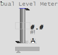 |
| Example Equipment Template | Meter |
| Associated Composite Genie | Meter.xml |
| Equipment.Items that the Genie expects | OPORHigh, ORLow, ORDspPRHigh, PRLowOPTrack, PVTrackPVSPFBCtrlMode, CtrlModeDefRunStatusEqStatusTrackDsp |
| Equipment Parameters the Equipment Items Expect | InternalIODeviceCicodeIODeviceEqStatusFuncCtrlModeRangeAlarm Limits |
| Associated Faceplate(s) | Analog ControllerAnalog Indicator |
| Equipment.Items that the Faceplate Expects | OPORHigh, ORLow, ORDspPRHigh, PRLowOPTrack, PVTrack, TrackDspPVSPCtrlMode, CtrlModeDefAutoCmd, ManCmd, CasCmd RunStatusOOS, OOSDisabled |
Configuration Tasks
- Create equipment and organize equipment in a hierarchy: Create equipment instances for the required objects, and organize the equipment in a hierarchy. Objects can be referred to by their name when you add Composite Genies to a graphics page. You can add one or more instances of an equipment to a page.
- Associate PLC Alarm Limits for Meters: This is an optional task that is required if you want to use PLC alarm limits instead of the standard analog alarm limits.
- Insert a Composite Genie: Create graphics pages with instances of Composite Genies that are associated with the equipment you have defined in your project.
- Create a new faceplate: Add a faceplate for the equipment to allow operators to engage with the equipment at runtime.
- Write Cicode functions to initialize PR and OR values. Refer to the Cicode Reference Online help for more information. It is recommended that for a Dual Level meter you set these values on both meters to the same value.
Presentation Options
The following presentation options are available for this object.
| Option | Description |
|---|---|
| Meter Type | From the dropdown list, select Dual Level. |
| Reference Equipment Name | Enter the full name and path for the equipment associated with the dual meter. The path and name should be prefixed with the equipment’s cluster name for multi-cluster systems. You can enter a maximum of 160 characters for this option. |
| Equipment Name and Equipment #2 Name | Enter the full name and path of the two equipment objects. You can enter a maximum of 160 characters for this option. |
| Equipment Item Prefix and Equipment #2 Item Prefix | Prefix applied to the equipment item name. This allows for displaying multiple values for a single piece of equipment. For example, you want to create two meters to monitor power or voltage for a single pump. You would create two meters on the pump and assign the equipment item prefix “Power1” and “Power2” or “Voltage1” and “Voltage2”. So, the PV values for the meters would be Power1PV, Power2PV, etc, respectively.Note: To get a meter with a prefix to work correctly, you need to create tags with the required item names. From the example above, you will need to create the tags Power1PV, Power2PV and so on.The following equipment item names can be prefixed: PV OP ORDsp TrackDsp FB PRLow PRHigh ORLow ORHigh SP PVTrack FullScale OPTrack Timer PVTarget |
| Size | Size of the meter object image - small or large |
| Orientation | Select the orientation that is appropriate for the presentation of the object on the graphics page. |
| Display Label | Use this setting to display a label at the selected position. Select None if you do not want to display a label. |
| Label | Enter the text that will display at the location specified in Display Label field. You can enter a maximum of 30 characters for this option. |
| Display Status Indicator | Select the location to display a status indicator. Select None if you do not wish to see the status indicator. For more information, see Status Indicators. |
| Display Process Variable | Select to display a process variable (numeric PV) with the meter. This option is selected by default. |
| Display Control Mode | Select this option to display the Controller Mode Indicator. On selecting this option the “Display Control Readback” option box is also displayed. The Display Control Readback Indicator represents the actual output for the controller. |
| Display Controller Output | Select to display an output indicator with the meter. For more information, see Output Bar. |
| Display Setpoint | Select to display a setpoint indicator with the meter. |
| Display OOS | Select to display Out of Service indicator. |
| Display Control Readback | Select to display a readback indicator (also known as feedback indicator) with the meter. |
| Mirrored | Inserts a mirror image of the meter based on the selected presentation options. |
Note: The Control Mode, PV and OP bar take values only from Equipment Name. Equipment Name #2 is only used to display the height of the second bar (the light grey bar).
Flow Meter
The flow indication is presented on a linear scale, containing a “floating ball” PV indicator like commonly found physical flow meters. The meter limit markers will appear only if there are no alarm limits shown, in order to better define the meter range visually.
| Property | Description |
|---|---|
| Name | Flow |
| Graphical Representation | /AVEVA%20Plant%20SCADA/Bin/Help/SCADA%20Help/Content/images/Meters_Flow_122x176.png) |
| Example Equipment Template | Meter |
| Associated Composite Genie | Meter.xml |
| Equipment.Items that the Genie expects | OPORHigh, ORLow, ORDspPRHigh, PRLowOPTrack, PVTrackPVSPFBCtrlMode, CtrlModeDefRunStatusEqStatusTrackDspTimer, TimerExp |
| Equipment Parameters the Equipment Items Expect | InternalIODeviceCicodeIODeviceEqStatusFuncCtrlModeRangeAlarm Limits |
| Associated Faceplate(s) | Analog ControllerAnalog Indicator |
| Equipment.Items that the Faceplate Expects | OPORHigh, ORLow, ORDspPRHigh, PRLowOPTrack, PVTrack, TrackDspPVSPCtrlMode, CtrlModeDefAutoCmd, ManCmd, CasCmd RunStatusOOS, OOSDisabled |
Configuration Tasks
- Create equipment and organize equipment in a hierarchy: Create equipment instances for the required objects, and organize the equipment in a hierarchy. Objects can be referred to by their name when you add Composite Genies to a graphics page. You can add one or more instances of an equipment to a page.
- Associate PLC Alarm Limits for Meters: This is an optional task that is required if you want to use PLC alarm limits instead of the standard analog alarm limits.
- Insert a Composite Genie: Create graphics pages with instances of Composite Genies that are associated with the equipment you have defined in your project.
- Create a new faceplate: Add a faceplate for the equipment to allow operators to engage with the equipment at runtime.
- Write Cicode functions to initialize PR and OR values. Refer to the Cicode Reference Online help for more information. It is recommended that for a Dual Level meter you set these values on both meters to the same value.
Presentation Options
The following presentation options are available for this object.
| Option | Description |
|---|---|
| Meter Type | From the drop-down select one of the following meters: Level, Flow, Temperature, Pressure, Analyzer, Miscellaneous, Target, Deviation and Dual Level |
| Equipment Name | Enter a name for the equipment associated with the meter. You can enter a maximum of 160 characters for this option. |
| Equipment Item Prefix | Prefix applied to the equipment item name. This allows for displaying multiple values for a single piece of equipment. For example, you want to create three meters to monitor power, voltage and current for a single pump. You would create three meters on the pump and assign the equipment item prefix “Power”, “Voltage” and “Current”. So, the PV values for the meters would be PowerPV, VoltagePV and CurrentPV respectively.Note: To get a meter with a prefix to work correctly, you need to create tags with the required item names. From the example above, you will need to create the tags PowerPV, PowerOP, VoltagePV, VoltageOP, CurrentPV, CurrentOP and so on.The following equipment item names (where applicable) can be prefixed: FB FullScale OP ORDsp ORLow ORHigh PRLow PRHigh PV PVTrack PVTarget SP Timer TrackDsp |
| Size | Size of the meter object image - small or large |
| Orientation | Select the orientation that is appropriate for the presentation of the object on the graphics page. |
| Display Label | Use this setting to display a label at the selected position. Select None if you do not want to display a label. |
| Label | Enter the text that will display at the location specified in Display Label field. You can enter a maximum of 30 characters for this option. |
| Display Alarm Indicator | Select this option to display an alarm border around the Genie. |
| Display Alarm Flag | Use this setting to display an alarm flag at the selected position. Note: If you select the same position for the alarm flag and Display Status indicator (see below), they will overlap. The alarm flag will not be visible. |
| Display Status Indicator | Use this setting to display a status indicator at the selected location. Select None if you do not want to display the status indicator. For more information, see Status Indicators. |
| Display Process Variable | Select to display a process variable (numeric PV) with the meter. This option is selected by default. |
| Display Control Mode | Select this option to display the Controller Mode Indicator. On selecting this option the Display Control Readback option box is also displayed. The Display Control Readback Indicator represents the actual output for the controller. |
| Display Controller Output | Select to display an output indicator with the meter. For more information, see Output Bar. |
| Display Setpoint | Select to display a setpoint indicator with the meter. |
| Display OOS | Select to display Out of Service indicator. |
| Display Differential Indication | Select to display an indicator when a differential reading is detected. This is visible only on Pressure and Temperature meters. For more information, see Meter Special Elements. |
| Descriptor | Enter a short 3-character text descriptor to indicate what is being measured. If left blank no descriptor will be displayed. This is visible only on Miscellaneous, Deviation and Analyzer meters. |
| Display Clock Timer | Select to display a clock timer on the meter. This is visible only on Analyzer meters. For more information, see Meter Special Elements. |
| Display Control Readback | Select to display a readback indicator (also known as feedback indicator) with the meter. |
| Display Trend | Select this option to display a Trend object with the meter. On selecting this option, the Trend Type dropdown is displayed. Select either Tail or Full.Note: When the Display Trend option is selected, the Mirrored option is not available. |
| Trend Type | Select the type of trend to be displayed with the meter: Tail or Full. |
| Mirrored | Inserts a mirror image of the meter based on the selected presentation options. |
Level Meter
The meter symbol for a Level meter is a narrow box shape that resembles a “skinny” vessel. The graphical PV is shown as a darker fill within the vessel. The fill rises and falls to indicate the actual level.
Level meters are provided in both vertical and horizontal orientations, although it is expected they will be used primarily in the vertical orientation.
| Property | Description |
|---|---|
| Name | Level |
| Graphical Representation | 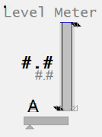 |
| Example Equipment Template | Meter |
| Associated Composite Genie | Meter.xml |
| Equipment.Items that the Genie expects | OPORHigh, ORLow, ORDspPRHigh, PRLowOPTrack, PVTrackPVSPFBCtrlMode, CtrlModeDefRunStatusEqStatusTrackDspTimer, TimerExp |
| Equipment Parameters the Equipment Items Expect | InternalIODeviceCicodeIODeviceEqStatusFuncCtrlModeRangeAlarm Limits |
| Associated Faceplate(s) | Analog ControllerAnalog Indicator |
| Equipment.Items that the Faceplate Expects | OPORHigh, ORLow, ORDspPRHigh, PRLowOPTrack, PVTrack, TrackDspPVSPCtrlMode, CtrlModeDefAutoCmd, ManCmd, CasCmd RunStatusOOS, OOSDisabled |
Configuration Tasks
- Create equipment and organize equipment in a hierarchy: Create equipment instances for the required objects, and organize the equipment in a hierarchy. Objects can be referred to by their name when you add Composite Genies to a graphics page. You can add one or more instances of an equipment to a page.
- Associate PLC Alarm Limits for Meters: This is an optional task that is required if you want to use PLC alarm limits instead of the standard analog alarm limits.
- Insert a Composite Genie: Create graphics pages with instances of Composite Genies that are associated with the equipment you have defined in your project.
- Create a new faceplate: Add a faceplate for the equipment to allow operators to engage with the equipment at runtime.
- Write Cicode functions to initialize PR and OR values. Refer to the Cicode Reference Online help for more information. It is recommended that for a Dual Level meter you set these values on both meters to the same value.
Presentation Options
The following presentation options are available for this object.
| Option | Description |
|---|---|
| Meter Type | From the drop-down select one of the following meters: Level, Flow, Temperature, Pressure, Analyzer, Miscellaneous, Target, Deviation and Dual Level |
| Equipment Name | Enter a name for the equipment associated with the meter. You can enter a maximum of 160 characters for this option. |
| Equipment Item Prefix | Prefix applied to the equipment item name. This allows for displaying multiple values for a single piece of equipment. For example, you want to create three meters to monitor power, voltage and current for a single pump. You would create three meters on the pump and assign the equipment item prefix “Power”, “Voltage” and “Current”. So, the PV values for the meters would be PowerPV, VoltagePV and CurrentPV respectively.Note: To get a meter with a prefix to work correctly, you need to create tags with the required item names. From the example above, you will need to create the tags PowerPV, PowerOP, VoltagePV, VoltageOP, CurrentPV, CurrentOP and so on.The following equipment item names (where applicable) can be prefixed: FB FullScale OP ORDsp ORLow ORHigh PRLow PRHigh PV PVTrack PVTarget SP Timer TrackDsp |
| Size | Size of the meter object image - small or large |
| Orientation | Select the orientation that is appropriate for the presentation of the object on the graphics page. |
| Display Label | Use this setting to display a label at the selected position. Select None if you do not want to display a label. |
| Label | Enter the text that will display at the location specified in Display Label field. You can enter a maximum of 30 characters for this option. |
| Display Alarm Indicator | Select this option to display an alarm border around the Genie. |
| Display Alarm Flag | Use this setting to display an alarm flag at the selected position. Note: If you select the same position for the alarm flag and Display Status indicator (see below), they will overlap. The alarm flag will not be visible. |
| Display Status Indicator | Use this setting to display a status indicator at the selected location. Select None if you do not want to display the status indicator. For more information, see Status Indicators. |
| Display Process Variable | Select to display a process variable (numeric PV) with the meter. This option is selected by default. |
| Display Control Mode | Select this option to display the Controller Mode Indicator. On selecting this option the Display Control Readback option box is also displayed. The Display Control Readback Indicator represents the actual output for the controller. |
| Display Controller Output | Select to display an output indicator with the meter. For more information, see Output Bar. |
| Display Setpoint | Select to display a setpoint indicator with the meter. |
| Display OOS | Select to display Out of Service indicator. |
| Display Differential Indication | Select to display an indicator when a differential reading is detected. This is visible only on Pressure and Temperature meters. For more information, see Meter Special Elements. |
| Descriptor | Enter a short 3-character text descriptor to indicate what is being measured. If left blank no descriptor will be displayed. This is visible only on Miscellaneous, Deviation and Analyzer meters. |
| Display Clock Timer | Select to display a clock timer on the meter. This is visible only on Analyzer meters. For more information, see Meter Special Elements. |
| Display Control Readback | Select to display a readback indicator (also known as feedback indicator) with the meter. |
| Display Trend | Select this option to display a Trend object with the meter. On selecting this option, the Trend Type dropdown is displayed. Select either Tail or Full.Note: When the Display Trend option is selected, the Mirrored option is not available. |
| Trend Type | Select the type of trend to be displayed with the meter: Tail or Full. |
| Mirrored | Inserts a mirror image of the meter based on the selected presentation options. |
Miscellaneous Meter
The miscellaneous meter indication is presented on a linear scale, containing a filled rectangle as a PV indicator. The miscellaneous meter is usually used to represent readings that do not have a dedicated meter type (e.g., weight, speed, torque, etc.).
| Property | Description |
|---|---|
| Name | Miscellaneous |
| Graphical Representation | 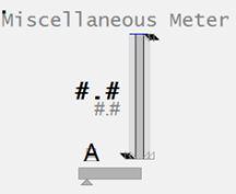 |
| Example Equipment Template | Meter |
| Associated Composite Genie | Meter.xml |
| Equipment.Items that the Genie expects | OPORHigh, ORLow, ORDspPRHigh, PRLowOPTrack, PVTrackPVSPFBCtrlMode, CtrlModeDefRunStatusEqStatusTrackDsp |
| Equipment Parameters the Equipment Items Expect | InternalIODeviceCicodeIODeviceEqStatusFuncCtrlModeRangeAlarm Limits |
| Associated Faceplate(s) | Analog ControllerAnalog Indicator |
| Equipment.Items that the Faceplate Expects | OPORHigh, ORLow, ORDspPRHigh, PRLowOPTrack, PVTrack, TrackDspPVSPCtrlMode, CtrlModeDefAutoCmd, ManCmd, CasCmd RunStatusOOS, OOSDisabled |
Configuration Tasks
- Create equipment and organize equipment in a hierarchy: Create equipment instances for the required objects, and organize the equipment in a hierarchy. Objects can be referred to by their name when you add Composite Genies to a graphics page. You can add one or more instances of an equipment to a page.
- Associate PLC Alarm Limits for Meters: This is an optional task that is required if you want to use PLC alarm limits instead of the standard analog alarm limits.
- Insert a Composite Genie: Create graphics pages with instances of Composite Genies that are associated with the equipment you have defined in your project.
- Create a new faceplate: Add a faceplate for the equipment to allow operators to engage with the equipment at runtime.
- Write Cicode functions to initialize PR and OR values. Refer to the Cicode Reference Online help for more information. It is recommended that for a Dual Level meter you set these values on both meters to the same value.
Presentation Options
The following presentation options are available for this object.
| Option | Description |
|---|---|
| Meter Type | From the drop-down select one of the following meters: Level, Flow, Temperature, Pressure, Analyzer, Miscellaneous, Target, Deviation and Dual Level |
| Equipment Name | Enter a name for the equipment associated with the meter. You can enter a maximum of 160 characters for this option. |
| Equipment Item Prefix | Prefix applied to the equipment item name. This allows for displaying multiple values for a single piece of equipment. For example, you want to create three meters to monitor power, voltage and current for a single pump. You would create three meters on the pump and assign the equipment item prefix “Power”, “Voltage” and “Current”. So, the PV values for the meters would be PowerPV, VoltagePV and CurrentPV respectively.Note: To get a meter with a prefix to work correctly, you need to create tags with the required item names. From the example above, you will need to create the tags PowerPV, PowerOP, VoltagePV, VoltageOP, CurrentPV, CurrentOP and so on.The following equipment item names (where applicable) can be prefixed: FB FullScale OP ORDsp ORLow ORHigh PRLow PRHigh PV PVTrack PVTarget SP Timer TrackDsp |
| Size | Size of the meter object image - small or large |
| Orientation | Select the orientation that is appropriate for the presentation of the object on the graphics page. |
| Display Label | Use this setting to display a label at the selected position. Select None if you do not want to display a label. |
| Label | Enter the text that will display at the location specified in Display Label field. You can enter a maximum of 30 characters for this option. |
| Display Alarm Indicator | Select this option to display an alarm border around the Genie. |
| Display Alarm Flag | Use this setting to display an alarm flag at the selected position. Note: If you select the same position for the alarm flag and Display Status indicator (see below), they will overlap. The alarm flag will not be visible. |
| Display Status Indicator | Use this setting to display a status indicator at the selected location. Select None if you do not want to display the status indicator. For more information, see Status Indicators. |
| Display Process Variable | Select to display a process variable (numeric PV) with the meter. This option is selected by default. |
| Display Control Mode | Select this option to display the Controller Mode Indicator. On selecting this option the Display Control Readback option box is also displayed. The Display Control Readback Indicator represents the actual output for the controller. |
| Display Controller Output | Select to display an output indicator with the meter. For more information, see Output Bar. |
| Display Setpoint | Select to display a setpoint indicator with the meter. |
| Display OOS | Select to display Out of Service indicator. |
| Display Differential Indication | Select to display an indicator when a differential reading is detected. This is visible only on Pressure and Temperature meters. For more information, see Meter Special Elements. |
| Descriptor | Enter a short 3-character text descriptor to indicate what is being measured. If left blank no descriptor will be displayed. This is visible only on Miscellaneous, Deviation and Analyzer meters. |
| Display Clock Timer | Select to display a clock timer on the meter. This is visible only on Analyzer meters. For more information, see Meter Special Elements. |
| Display Control Readback | Select to display a readback indicator (also known as feedback indicator) with the meter. |
| Display Trend | Select this option to display a Trend object with the meter. On selecting this option, the Trend Type dropdown is displayed. Select either Tail or Full.Note: When the Display Trend option is selected, the Mirrored option is not available. |
| Trend Type | Select the type of trend to be displayed with the meter: Tail or Full. |
| Mirrored | Inserts a mirror image of the meter based on the selected presentation options. |
Pressure Meter
Pressure meters can be used to show regular pressure readings, or differential pressure readings.
| Property | Description |
|---|---|
| Name | Pressure |
| Graphical Representation | 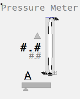 |
| Example Equipment Template | Meter |
| Associated Composite Genie | Meter.xml |
| Equipment.Items that the Genie expects | OPORHigh, ORLow, ORDspPRHigh, PRLowOPTrack, PVTrackPVSPFBCtrlMode, CtrlModeDefRunStatusEqStatusTrackDsp |
| Equipment Parameters the Equipment Items Expect | InternalIODeviceCicodeIODeviceEqStatusFuncCtrlModeRangeAlarm Limits |
| Associated Faceplate(s) | Analog ControllerAnalog Indicator |
| Equipment.Items that the Faceplate Expects | OPORHigh, ORLow, ORDspPRHigh, PRLowOPTrack, PVTrack, TrackDspPVSPCtrlMode, CtrlModeDefAutoCmd, ManCmd, CasCmd RunStatusOOS, OOSDisabled |
Configuration Tasks
- Create equipment and organize equipment in a hierarchy: Create equipment instances for the required objects, and organize the equipment in a hierarchy. Objects can be referred to by their name when you add Composite Genies to a graphics page. You can add one or more instances of an equipment to a page.
- Associate PLC Alarm Limits for Meters: This is an optional task that is required if you want to use PLC alarm limits instead of the standard analog alarm limits.
- Insert a Composite Genie: Create graphics pages with instances of Composite Genies that are associated with the equipment you have defined in your project.
- Create a new faceplate: Add a faceplate for the equipment to allow operators to engage with the equipment at runtime.
- Write Cicode functions to initialize PR and OR values. Refer to the Cicode Reference Online help for more information. It is recommended that for a Dual Level meter you set these values on both meters to the same value.
Presentation Options
The following presentation options are available for this object.
| Option | Description |
|---|---|
| Meter Type | From the drop-down select one of the following meters: Level, Flow, Temperature, Pressure, Analyzer, Miscellaneous, Target, Deviation and Dual Level |
| Equipment Name | Enter a name for the equipment associated with the meter. You can enter a maximum of 160 characters for this option. |
| Equipment Item Prefix | Prefix applied to the equipment item name. This allows for displaying multiple values for a single piece of equipment. For example, you want to create three meters to monitor power, voltage and current for a single pump. You would create three meters on the pump and assign the equipment item prefix “Power”, “Voltage” and “Current”. So, the PV values for the meters would be PowerPV, VoltagePV and CurrentPV respectively.Note: To get a meter with a prefix to work correctly, you need to create tags with the required item names. From the example above, you will need to create the tags PowerPV, PowerOP, VoltagePV, VoltageOP, CurrentPV, CurrentOP and so on.The following equipment item names (where applicable) can be prefixed: FB FullScale OP ORDsp ORLow ORHigh PRLow PRHigh PV PVTrack PVTarget SP Timer TrackDsp |
| Size | Size of the meter object image - small or large |
| Orientation | Select the orientation that is appropriate for the presentation of the object on the graphics page. |
| Display Label | Use this setting to display a label at the selected position. Select None if you do not want to display a label. |
| Label | Enter the text that will display at the location specified in Display Label field. You can enter a maximum of 30 characters for this option. |
| Display Alarm Indicator | Select this option to display an alarm border around the Genie. |
| Display Alarm Flag | Use this setting to display an alarm flag at the selected position. Note: If you select the same position for the alarm flag and Display Status indicator (see below), they will overlap. The alarm flag will not be visible. |
| Display Status Indicator | Use this setting to display a status indicator at the selected location. Select None if you do not want to display the status indicator. For more information, see Status Indicators. |
| Display Process Variable | Select to display a process variable (numeric PV) with the meter. This option is selected by default. |
| Display Control Mode | Select this option to display the Controller Mode Indicator. On selecting this option the Display Control Readback option box is also displayed. The Display Control Readback Indicator represents the actual output for the controller. |
| Display Controller Output | Select to display an output indicator with the meter. For more information, see Output Bar. |
| Display Setpoint | Select to display a setpoint indicator with the meter. |
| Display OOS | Select to display Out of Service indicator. |
| Display Differential Indication | Select to display an indicator when a differential reading is detected. This is visible only on Pressure and Temperature meters. For more information, see Meter Special Elements. |
| Descriptor | Enter a short 3-character text descriptor to indicate what is being measured. If left blank no descriptor will be displayed. This is visible only on Miscellaneous, Deviation and Analyzer meters. |
| Display Clock Timer | Select to display a clock timer on the meter. This is visible only on Analyzer meters. For more information, see Meter Special Elements. |
| Display Control Readback | Select to display a readback indicator (also known as feedback indicator) with the meter. |
| Display Trend | Select this option to display a Trend object with the meter. On selecting this option, the Trend Type dropdown is displayed. Select either Tail or Full.Note: When the Display Trend option is selected, the Mirrored option is not available. |
| Trend Type | Select the type of trend to be displayed with the meter: Tail or Full. |
| Mirrored | Inserts a mirror image of the meter based on the selected presentation options. |
Target Meter
The Target meter is used to show deviations from setpoint in level.
| Property | Description |
|---|---|
| Name | Target |
| Graphical Representation | 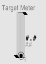 |
| Example Equipment Template | TargetMeter |
| Associated Composite Genie | Meter.xml |
| Equipment.Items that the Genie expects | OPORHigh, ORLow, ORDspPRHigh, PRLowOPTrack, PVTrackPVSPFBCtrlMode, CtrlModeDefRunStatusEqStatusTrackDsp |
| Equipment Parameters the Equipment Items Expect | InternalIODeviceCicodeIODeviceEqStatusFuncCtrlModeRangeAlarm Limits |
| Associated Faceplate(s) | Analog ControllerAnalog Indicator |
| Equipment.Items that the Faceplate Expects | OPORHigh, ORLow, ORDspPRHigh, PRLowOPTrack, PVTrack, TrackDspPVSPCtrlMode, CtrlModeDefAutoCmd, ManCmd, CasCmd RunStatusOOS, OOSDisabled |
Configuration Tasks
- Create equipment and organize equipment in a hierarchy: Create equipment instances for the required objects, and organize the equipment in a hierarchy. Objects can be referred to by their name when you add Composite Genies to a graphics page. You can add one or more instances of an equipment to a page.
- Associate PLC Alarm Limits for Meters: This is an optional task that is required if you want to use PLC alarm limits instead of the standard analog alarm limits.
- Insert a Composite Genie: Create graphics pages with instances of Composite Genies that are associated with the equipment you have defined in your project.
- Create a new faceplate: Add a faceplate for the equipment to allow operators to engage with the equipment at runtime.
- Write Cicode functions to initialize PR and OR values. Refer to the Cicode Reference Online help for more information. It is recommended that for a Dual Level meter you set these values on both meters to the same value.
Presentation Options
The following presentation options are available for this object.
| Option | Description |
|---|---|
| Meter Type | From the drop-down select one of the following meters: Level, Flow, Temperature, Pressure, Analyzer, Miscellaneous, Target, Deviation and Dual Level |
| Equipment Name | Enter a name for the equipment associated with the meter. You can enter a maximum of 160 characters for this option. |
| Equipment Item Prefix | Prefix applied to the equipment item name. This allows for displaying multiple values for a single piece of equipment. For example, you want to create three meters to monitor power, voltage and current for a single pump. You would create three meters on the pump and assign the equipment item prefix “Power”, “Voltage” and “Current”. So, the PV values for the meters would be PowerPV, VoltagePV and CurrentPV respectively.Note: To get a meter with a prefix to work correctly, you need to create tags with the required item names. From the example above, you will need to create the tags PowerPV, PowerOP, VoltagePV, VoltageOP, CurrentPV, CurrentOP and so on.The following equipment item names (where applicable) can be prefixed: FB FullScale OP ORDsp ORLow ORHigh PRLow PRHigh PV PVTrack PVTarget SP Timer TrackDsp |
| Size | Size of the meter object image - small or large |
| Orientation | Select the orientation that is appropriate for the presentation of the object on the graphics page. |
| Display Label | Use this setting to display a label at the selected position. Select None if you do not want to display a label. |
| Label | Enter the text that will display at the location specified in Display Label field. You can enter a maximum of 30 characters for this option. |
| Display Alarm Indicator | Select this option to display an alarm border around the Genie. |
| Display Alarm Flag | Use this setting to display an alarm flag at the selected position. Note: If you select the same position for the alarm flag and Display Status indicator (see below), they will overlap. The alarm flag will not be visible. |
| Display Status Indicator | Use this setting to display a status indicator at the selected location. Select None if you do not want to display the status indicator. For more information, see Status Indicators. |
| Display Process Variable | Select to display a process variable (numeric PV) with the meter. This option is selected by default. |
| Display Control Mode | Select this option to display the Controller Mode Indicator. On selecting this option the Display Control Readback option box is also displayed. The Display Control Readback Indicator represents the actual output for the controller. |
| Display Controller Output | Select to display an output indicator with the meter. For more information, see Output Bar. |
| Display Setpoint | Select to display a setpoint indicator with the meter. |
| Display OOS | Select to display Out of Service indicator. |
| Display Differential Indication | Select to display an indicator when a differential reading is detected. This is visible only on Pressure and Temperature meters. For more information, see Meter Special Elements. |
| Descriptor | Enter a short 3-character text descriptor to indicate what is being measured. If left blank no descriptor will be displayed. This is visible only on Miscellaneous, Deviation and Analyzer meters. |
| Display Clock Timer | Select to display a clock timer on the meter. This is visible only on Analyzer meters. For more information, see Meter Special Elements. |
| Display Control Readback | Select to display a readback indicator (also known as feedback indicator) with the meter. |
| Display Trend | Select this option to display a Trend object with the meter. On selecting this option, the Trend Type dropdown is displayed. Select either Tail or Full.Note: When the Display Trend option is selected, the Mirrored option is not available. |
| Trend Type | Select the type of trend to be displayed with the meter: Tail or Full. |
| Mirrored | Inserts a mirror image of the meter based on the selected presentation options. |
Temperature Meter
Temperatures are indicated on a linear scale. Temperature meters can be used to show regular temperature readings, or differential temperature readings.
| Property | Description |
|---|---|
| Name | Deviation |
| Graphical Representation | 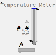 |
| Example Equipment Template | Meter |
| Associated Composite Genie | Meter.xml |
| Equipment.Items that the Genie expects | OPORHigh, ORLow, ORDspPRHigh, PRLowOPTrack, PVTrackPVSPFBCtrlMode, CtrlModeDefRunStatusEqStatusTrackDsp |
| Equipment Parameters the Equipment Items Expect | InternalIODeviceCicodeIODeviceEqStatusFuncCtrlModeRangeAlarm Limits |
| Associated Faceplate(s) | Analog ControllerAnalog Indicator |
| Equipment.Items that the Faceplate Expects | OPORHigh, ORLow, ORDspPRHigh, PRLowOPTrack, PVTrack, TrackDspPVSPCtrlMode, CtrlModeDefAutoCmd, ManCmd, CasCmd RunStatusOOS, OOSDisabled |
Configuration Tasks
- Create equipment and organize equipment in a hierarchy: Create equipment instances for the required objects, and organize the equipment in a hierarchy. Objects can be referred to by their name when you add Composite Genies to a graphics page. You can add one or more instances of an equipment to a page.
- Associate PLC Alarm Limits for Meters: This is an optional task that is required if you want to use PLC alarm limits instead of the standard analog alarm limits.
- Insert a Composite Genie: Create graphics pages with instances of Composite Genies that are associated with the equipment you have defined in your project.
- Create a new faceplate: Add a faceplate for the equipment to allow operators to engage with the equipment at runtime.
- Write Cicode functions to initialize PR and OR values. Refer to the Cicode Reference Online help for more information. It is recommended that for a Dual Level meter you set these values on both meters to the same value.
Presentation Options
The following presentation options are available for this object.
| Option | Description |
|---|---|
| Meter Type | From the drop-down select one of the following meters: Level, Flow, Temperature, Pressure, Analyzer, Miscellaneous, Target, Deviation and Dual Level |
| Equipment Name | Enter a name for the equipment associated with the meter. You can enter a maximum of 160 characters for this option. |
| Equipment Item Prefix | Prefix applied to the equipment item name. This allows for displaying multiple values for a single piece of equipment. For example, you want to create three meters to monitor power, voltage and current for a single pump. You would create three meters on the pump and assign the equipment item prefix “Power”, “Voltage” and “Current”. So, the PV values for the meters would be PowerPV, VoltagePV and CurrentPV respectively.Note: To get a meter with a prefix to work correctly, you need to create tags with the required item names. From the example above, you will need to create the tags PowerPV, PowerOP, VoltagePV, VoltageOP, CurrentPV, CurrentOP and so on.The following equipment item names (where applicable) can be prefixed: FB FullScale OP ORDsp ORLow ORHigh PRLow PRHigh PV PVTrack PVTarget SP Timer TrackDsp |
| Size | Size of the meter object image - small or large |
| Orientation | Select the orientation that is appropriate for the presentation of the object on the graphics page. |
| Display Label | Use this setting to display a label at the selected position. Select None if you do not want to display a label. |
| Label | Enter the text that will display at the location specified in Display Label field. You can enter a maximum of 30 characters for this option. |
| Display Alarm Indicator | Select this option to display an alarm border around the Genie. |
| Display Alarm Flag | Use this setting to display an alarm flag at the selected position. Note: If you select the same position for the alarm flag and Display Status indicator (see below), they will overlap. The alarm flag will not be visible. |
| Display Status Indicator | Use this setting to display a status indicator at the selected location. Select None if you do not want to display the status indicator. For more information, see Status Indicators. |
| Display Process Variable | Select to display a process variable (numeric PV) with the meter. This option is selected by default. |
| Display Control Mode | Select this option to display the Controller Mode Indicator. On selecting this option the Display Control Readback option box is also displayed. The Display Control Readback Indicator represents the actual output for the controller. |
| Display Controller Output | Select to display an output indicator with the meter. For more information, see Output Bar. |
| Display Setpoint | Select to display a setpoint indicator with the meter. |
| Display OOS | Select to display Out of Service indicator. |
| Display Differential Indication | Select to display an indicator when a differential reading is detected. This is visible only on Pressure and Temperature meters. For more information, see Meter Special Elements. |
| Descriptor | Enter a short 3-character text descriptor to indicate what is being measured. If left blank no descriptor will be displayed. This is visible only on Miscellaneous, Deviation and Analyzer meters. |
| Display Clock Timer | Select to display a clock timer on the meter. This is visible only on Analyzer meters. For more information, see Meter Special Elements. |
| Display Control Readback | Select to display a readback indicator (also known as feedback indicator) with the meter. |
| Display Trend | Select this option to display a Trend object with the meter. On selecting this option, the Trend Type dropdown is displayed. Select either Tail or Full.Note: When the Display Trend option is selected, the Mirrored option is not available. |
| Trend Type | Select the type of trend to be displayed with the meter: Tail or Full. |
| Mirrored | Inserts a mirror image of the meter based on the selected presentation options. |