PACFramework
Class DOVAR: Discrete Process Output Variable
CLSID=16#1020
General Description
This class implements functions for processing and writing output data to DOCH and handling diagnostic information received from DOCH. These functions include processing diagnostic information from DOCH, signal inversion if needed, and managing forcing and simulation modes.
If implementation differences are required, use other CLSIDs in the format 16#102x.
General Requirements for DOVAR Functions
Functional Requirements
Operating Modes
The DOVAR class must support the following modes (sub-modes):
- output writing/simulation
- non-forced/forced
In all modes except simulation, the value transmitted to the linked DOCH channel is taken from STA.VRAW.
The normal mode is a combination of “output writing” and “non-forced” modes. In this mode, the value of STA.VAL depends on the user program result, passes through processing functions, and is written to STA.VRAW, which is then sent to the physical DOCH channel.
In simulation mode (STA.SML=TRUE), STA.VAL bypasses processing functions and does not write to STA.VRAW. In other words, STA.VAL has no effect on the physical output. Simulation mode also changes the STA.SML state of the linked channel.
In forced mode (STA.FRC=TRUE), STA.VAL is changed only via HMI debug windows and has the highest priority; the user program has no effect on STA.VAL. When the force bit is active, PLC_CFG.CNTFRC increments by 1.
Signal Inversion
If PRM.INVERSE=TRUE, then STA.VAL = NOT STA.VRAW.
Channel Link Monitoring
STA.DLNK=TRUE indicates that the variable is linked to a channel.
Variable Activity
Variable activity is determined by STA.ENBL = NOT PRM.DSBL AND DLNK. If inactive (STA.ENBL=FALSE), the following functions do not operate:
- output signal writing and transformation
- simulation
- invalidity alarm diagnostics and processing
Higher-level controllers (e.g., CM LVL2) must treat this variable as temporarily non-existent (decommissioned). For example, if the variable controls a valve solenoid, the CM will assume the variable is absent and may operate under a “monostable valve” algorithm.
Measurement Channel Diagnostics
The class provides measurement channel validity checking. When PRM.QALENBL=TRUE, STA.BAD directly depends on the linked channel’s STA.BAD. No other diagnostic methods are implemented in this variable class.
STA.BAD indicates a validity alarm. On a rising edge of the alarm, PLC_CFG.NWBAD=TRUE. While STA.BAD is active:
- The corresponding
PLC_CFG.BADbit is set PLC_CFG.CNTBADincrements by 1
Resetting PRM.QALENBL=FALSE disables the validity alarm check.
Recommendations for HMI Usage
An example of configuring discrete output variable functions on the HMI is shown below.
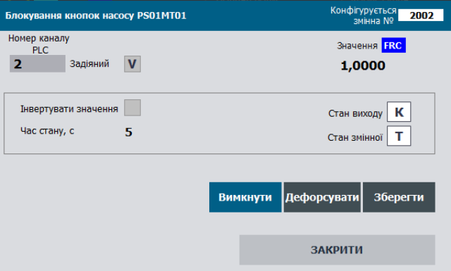
Figure: Example of configuring discrete output variable functions on the HMI.
General Variable Structure Requirements
DOVAR_HMI
| name | type | adr | bit | description |
|---|---|---|---|---|
| STA | UINT | 0 | states + load command bit DOVAR_STA |
DOVAR_CFG
| name | type | adr | bit | description |
|---|---|---|---|---|
| ID | UINT | 0 | Unique identifier | |
| CLSID | UINT | 1 | 16#1020 | |
| STA | UINT | 2 | status bits, same assignment as DOVAR_STA structure |
|
| STA_VRAW | BOOL | 2 | 0 | =1 – discrete output signal value on DOCH |
| STA_VALB | BOOL | 2 | 1 | =1 – output variable value after processing, can change externally in force mode |
| STA_BAD | BOOL | 2 | 2 | =1 – Data invalid |
| STA_ALDIS | BOOL | 2 | 3 | =1 – Alarm disabled |
| STA_DLNK | BOOL | 2 | 4 | =1 – linked to channel |
| STA_ENBL | BOOL | 2 | 5 | =1 – variable active |
| STA_b6 | BOOL | 2 | 6 | reserved |
| STA_VALPRV | BOOL | 2 | 7 | previous cycle value |
| STA_b8 | BOOL | 2 | 8 | reserved |
| STA_b9 | BOOL | 2 | 9 | reserved |
| STA_b10 | BOOL | 2 | 10 | reserved |
| STA_b11 | BOOL | 2 | 11 | reserved |
| STA_INBUF | BOOL | 2 | 12 | =1 – variable in buffer |
| STA_FRC | BOOL | 2 | 13 | =1 – force mode active |
| STA_SML | BOOL | 2 | 14 | =1 – simulation mode active |
| STA_CMDLOAD | BOOL | 2 | 15 | =1 – load command to buffer |
| VALI | INT | 3 | non-force: INT value; force: stored forced value | |
| PRM | UINT | 4 | configuration parameters, non-volatile | |
| PRM_b0 | BOOL | 4 | 0 | reserved |
| PRM_b1 | BOOL | 4 | 1 | reserved |
| PRM_INVERSE | BOOL | 4 | 2 | =1 – invert raw value |
| PRM_b3 | BOOL | 4 | 3 | reserved |
| PRM_b4 | BOOL | 4 | 4 | reserved |
| PRM_b5 | BOOL | 4 | 5 | reserved |
| PRM_QALENBL | BOOL | 4 | 6 | =1 – enable validity alarm |
| PRM_DSBL | BOOL | 4 | 7 | =1 – variable disabled |
| PRM_b8-15 | BOOL | 4 | 8-15 | reserved |
| CHID | UINT | 5 | logical DO channel number linked to variable, 0 = none | |
| CHIDDF | UINT | 6 | default logical DO channel number | |
| STEP1 | UINT | 7 | step number | |
| TSTEP1 | UDINT | 8 | step runtime in ms | |
| T_PREV | UDINT | 10 | previous call time in ms (from PLC_CFG.TQMS) |
Buffer Commands (see buffer structure):
| Attribute | Type | Bit | Description |
|---|---|---|---|
| CMD | UINT | Commands:16#0001: write 1 (force only)16#0002: write 0 (force only)16#0003: TOGGLE (force only)16#0100: read configuration16#0101: write configuration16#0102: write default value16#0300: toggle force16#0301: enable force16#0302: disable force16#0311: simulate16#0312: disable simulation |
Buffer Handling
Classic buffer handling must be implemented:
- A single buffer is recommended for all process variables.
- Buffer occupancy is checked by matching
CLSIDandID. - On buffer capture:
VARBUF.STA = DOVAR_CFG.STADOVAR_CFG.CMD = VARBUF.CMD(if non-zero to allow external commands)- physical channel status bits are read into
VARBUF.CH_STA = CHCFG.STA.
- Variable configuration should be read to the buffer upon:
- status bit
STA.CMDLOAD=TRUE - updating the variable already stored in the buffer with
VARBUF.CMD = 16#0100.
- status bit
- Variable configuration should be written from the buffer upon:
VARBUF.CMD = 16#0101.
Parametric bidirectional buffer handling VARBUFIN<->VARBUFOUT must also be implemented:
- Uses:
VARBUFIN(input) for processing commands (if CLSID & ID match) and writing to the variable.VARBUFOUT(output) for reading variable data uponVARBUFINread commands.
- A single pair should be used for all process variables.
- The buffer cannot be occupied since it uses separate IN/OUT buffers.
- Variable configuration should be read to
VARBUFOUTwhen:DOVARCFG.CLSID=VARBUFIN.CLSID,DOVARCFG.ID=VARBUFIN.ID, andVARBUFIN.CMD=16#100.
- Variable configuration should be written from
VARBUFINwhen:DOVARCFG.CLSID=VARBUFIN.CLSID,DOVARCFG.ID=VARBUFIN.ID, andVARBUFIN.CMD=16#101.
Interface Implementation Requirements
INOUT:
CHCFG– physical channel linked to the variableDOVARCFG– variable configuration structureDOVARHMI– HMI structure- If external variable access is unavailable inside functions, pass
PLC_CFG,VARBUF,VARBUFIN, andVARBUFOUT, or use alternative interfaces withinPLC_CFG.
Variable Initialization on First Cycle
ID, CHID, CHIDDF default values are written in the initvars program section:
"VAR".DOVAR1.ID := 2001;
"VAR".DOVAR1.CHID := 1;
"VAR".DOVAR1.CHIDDF := 1;
Additionally, initialization is performed inside the variable handling function, resulting in:
DOVARCFG.CLSID := 16#1020;- variable activation
DOVARCFG.PRM.DSBL := FALSE; - if
CHID=0, assign default:DOVARCFG.CHID := DOVARCFG.CHIDDF;.
User Program Implementation Requirements
- Process variable handling functions must be called on every cycle of the task to which they are assigned.
- On the first start (
PLC_CFG.SCN1), the variable identifierDOVAR_CFG.IDand the logical channel numberDOVAR_CFG.CHIDmust be initialized.
(*variable initialization on the first processing cycle*)
IF "SYS".PLCCFG.STA.SCN1 THEN
    #DOVARCFG.CLSID := 16#1020; (*assign class identifier*)
    #DOVARCFG.PRM.DSBL := FALSE; (*activate the variable*)
    #DOVARCFG.T_PREV := "SYS".PLCCFG.TQMS; (*store the call time*)
    IF #DOVARCFG.CHID = 0 THEN (*if the logical channel number is not set - assign the default value*)
        #DOVARCFG.CHID := #DOVARCFG.CHIDDF;
    END_IF;

    (*write the raw value from the channel for further processing*)
    IF #CHCFG.ID > 0 THEN
        #CHCFG.STA.VALB := #DOVARCFG.STA.VALB;
    ELSE
        #CHCFG.STA.VALB := 0;
    END_IF;

    #DOVARCFG.T_STEP1 := 0; (*reset step time*)
    #DOVARCFG.STEP1 := 400; (*switch to step DO=0*)

    (*define the variable ID range*)
    IF #DOVARCFG.ID>0 THEN
        IF #DOVARCFG.ID<"SYS".VARIDMIN THEN "SYS".VARIDMIN:=#DOVARCFG.ID; END_IF;
        IF #DOVARCFG.ID>"SYS".VARIDMAX THEN "SYS".VARIDMAX:=#DOVARCFG.ID; END_IF;
    END_IF;

    RETURN;
END_IF;

(*read status bits from the process variable into internal variables*)
#VRAW := #DOVARCFG.STA.VRAW;
#VAL := #DOVARCFG.STA.VALB;
#BAD := #DOVARCFG.STA.BAD;
#DLNK := #DOVARCFG.STA.DLNK;
#ENBL := #DOVARCFG.STA.ENBL;
#VALPRV := #DOVARCFG.STA.VALPRV;
#INBUF := #DOVARCFG.STA.INBUF;
#FRC := #DOVARCFG.STA.FRC;
#SML := #DOVARCFG.STA.SML;
#CMDLOAD := #DOVARCFG.STA.CMDLOAD;

(*read parameter bits from the process variable into internal variables*)
#PRM_INVERSE := #DOVARCFG.PRM.INVERSE;
#PRM_QALENBL := #DOVARCFG.PRM.QALENBL;
#PRM_DSBL := #DOVARCFG.PRM.DSBL;
#PRM_STATICMAP := #DOVARCFG.PRM.STATICMAP;

#INBUF := (#DOVARCFG.ID = "BUF".VARBUF.ID) AND (#DOVARCFG.CLSID = "BUF".VARBUF.CLSID); (*the variable is in the buffer if the variable ID and class ID match*)
#CMDLOAD := #DOVARHMI.STA.%X15; (*command to write to the buffer from the variable's HMI*)
#CMD := 0; (*reset the internal command*)
#DLNK := (#CHCFG.ID > 0); (*the variable is linked to the channel if the channel has a valid ID (not 0)*)
#VARENBL := NOT #PRM_DSBL AND #DLNK; (*the variable is active if linked to the channel and the disable parameter is not active*)
#VRAW := #CHCFG.STA.VALB; (*read the raw value from the channel*)
#T_STEPMS := #DOVARCFG.T_STEP1; (*store the cycle time in ms*)

(*ping-pong algorithm implementation*)
IF #DLNK THEN
    #CHCFG.STA.PNG := true;
    #CHCFG.VARID := #DOVARCFG.ID;
END_IF;

(*if the variable is inactive, do not count time, reset the state*)
IF NOT #VARENBL THEN
    #DOVARCFG.T_STEP1 := 0;
    #DOVARCFG.STEP1 := 400;
END_IF;

(*calculate the time between function calls based on the difference between the millisecond counter and the previous call time*)
#dT := "SYS".PLCCFG.TQMS - #DOVARCFG.T_PREV;

(*broadcast de-forcing*)
IF "SYS".PLCCFG.CMD = 16#4302 THEN
    #FRC := false; (*de-force the object type*)
END_IF;

(*select the configuration/control command source according to priority if commands arrive simultaneously*)
IF #CMDLOAD THEN (*buffer write command - from the HMI*)
    #CMD := 16#0100;
ELSIF #INBUF AND "BUF".VARBUF.CMD <> 0 THEN (*command from buffer*)
    #CMD := "BUF".VARBUF.CMD;
END_IF;
(*commands*)
CASE #CMD OF
    16#0001: (*write 1*)
        IF #FRC AND #INBUF THEN
            #DOVARCFG.VALI := 1;
            "BUF".VARBUF.VALR:=1.0;
            #VAL := true;
            #DOVARCFG.STEP1 := 401;
            #DOVARCFG.T_STEP1 := 0;
        END_IF;
    16#0002: (*write 0*)
        IF #FRC AND #INBUF THEN
            #DOVARCFG.VALI := 0;
            "BUF".VARBUF.VALR:=0.0;
            #VAL := false;
            #DOVARCFG.STEP1 := 400;
            #DOVARCFG.T_STEP1 := 0;
        END_IF;
    16#0003: (*TOGGLE*)
        IF #FRC AND #INBUF THEN
            IF #DOVARCFG.VALI > 0 THEN
                #DOVARCFG.VALI := 0;
                "BUF".VARBUF.VALR:=0.0;
                #VAL := false;
                #DOVARCFG.STEP1 := 400;
                #DOVARCFG.T_STEP1 := 0;
            ELSE
                #DOVARCFG.VALI := 1;
                "BUF".VARBUF.VALR:=1.0;
                #VAL := true;
                #DOVARCFG.STEP1 := 401;
                #DOVARCFG.T_STEP1 := 0;
            END_IF;
        END_IF;
    16#0100: (*read configuration*)
        (* MSG 200-Ok 400-Error
        // 200 - Data written
        // 201 - Data read
        // 403 - Channel already occupied
        // 404 - Channel number out of range
        // 405 - Static channel addressing active *)
        "BUF".VARBUF.MSG:=201;

        (*read variable ID and class ID*)
        "BUF".VARBUF.ID := #DOVARCFG.ID;
        "BUF".VARBUF.CLSID := #DOVARCFG.CLSID;

        (*read parameter bits*)
        "BUF".VARBUF.PRM.%X2 := #PRM_INVERSE;
        "BUF".VARBUF.PRM.%X6 := #PRM_QALENBL;
        "BUF".VARBUF.PRM.%X7 := #PRM_DSBL;
        "BUF".VARBUF.PRM.%X14 := #PRM_STATICMAP;

        (*read parameters*)
        "BUF".VARBUF.CHID := #DOVARCFG.CHID;

        (*read variable value for bumpless forcing*)
        "BUF".VARBUF.VALR := INT_TO_REAL(#DOVARCFG.VALI);

    16#0101: (*write configuration*)
        (* MSG 200-Ok 400-Error
        // 200 - Data written
        // 201 - Data read
        // 403 - Channel already occupied
        // 404 - Channel number out of range *)
        "BUF".VARBUF.MSG:=200;

        (*write parameter bits*)
        #PRM_INVERSE := "BUF".VARBUF.PRM.%X2;
        #PRM_QALENBL := "BUF".VARBUF.PRM.%X6;
        #PRM_DSBL := "BUF".VARBUF.PRM.%X7;
        #PRM_STATICMAP := "BUF".VARBUF.PRM.%X14;

        (*algorithm for changing the logical channel number with validity check*)
        IF NOT #PRM_STATICMAP THEN (*change logical channel number only if static addressing is inactive*)
            IF "BUF".VARBUF.CHID>=0 AND "BUF".VARBUF.CHID <= INT_TO_UINT("SYS".PLCCFG.DOCNT) THEN (*if channel number is within the valid range*)
                IF "SYS".CHDO["BUF".VARBUF.CHID].VARID = 0 THEN  (*if channel is free (VARID = 0)*)
                    #DOVARCFG.CHID := "BUF".VARBUF.CHID; (*change channel number*)
                ELSIF "BUF".VARBUF.CHID <> #DOVARCFG.CHID THEN (*else show channel occupied error*)
                    "BUF".VARBUF.MSG := 403;(* channel already occupied *)
                END_IF;
            ELSE
                "BUF".VARBUF.MSG := 404; (*channel number out of range*)
            END_IF;
        ELSIF "BUF".VARBUF.CHID <> #DOVARCFG.CHID THEN (*else show static addressing active error*)
            "BUF".VARBUF.MSG := 405;(* static channel addressing active *)
        END_IF;
        IF #INBUF THEN (*update channel number after write if variable is still in buffer*)
            "BUF".VARBUF.CHID := #DOVARCFG.CHID;
        END_IF;
    16#0102: (*write default value*)
        #DOVARCFG.CHID := #DOVARCFG.CHIDDF;
    16#0300: (*toggle forcing*)
        #FRC := NOT #FRC;
    16#0301: (*enable forcing*)
        #FRC := true;
    16#0302: (*disable forcing*)
        #FRC := false;
    16#0311: (*enable simulation*)
        #SML := true;
    16#0312: (*disable simulation*)
        #SML := false;
END_CASE;

(*value processing*)
IF #FRC THEN (*forcing mode*)
    IF #INBUF THEN
        #DOVARCFG.VALI := REAL_TO_INT("BUF".VARBUF.VALR);
    END_IF;
    #VAL := #DOVARCFG.VALI > 0;
    IF #VAL THEN
        #DOVARCFG.STEP1 := 401;
    ELSE
        #DOVARCFG.STEP1 := 400;
    END_IF;
ELSE (*non-forced value processing - normal variable operation*)
    IF #VAL THEN
        #DOVARCFG.VALI := 1;
        #DOVARCFG.STEP1 := 401;
    ELSE
        #DOVARCFG.VALI := 0;
        #DOVARCFG.STEP1 := 400;
    END_IF;
END_IF;

(*detect rising edge to reset step time*)
IF #VAL <> #VALPRV THEN
    #DOVARCFG.T_STEP1 := 0;
END_IF;

(*write value to physical channel only if variable is active*)
IF #VARENBL THEN
    IF #PRM_INVERSE THEN (*invert output if configured*)
        #VRAW := NOT #VAL;
    ELSE
        #VRAW := #VAL;
    END_IF;
    IF NOT #SML THEN (*in simulation mode, output value is not changed*)
        #CHCFG.STA.VALB := #VRAW;
    END_IF;
END_IF;

#BAD := #CHCFG.STA.BAD AND #PRM_QALENBL AND #VARENBL AND NOT #SML; (*validity alarm from linked physical channel*)

(*transmit alarms to PLCCFG for overall status bit and new alarm detection*)
IF #BAD THEN
    "SYS".PLCCFG.ALM1.BAD := true;
    "SYS".PLCCFG.CNTBAD := "SYS".PLCCFG.CNTBAD + 1;
    IF NOT #DOVARCFG.STA.BAD THEN
        "SYS".PLCCFG.ALM1.NWBAD := true;
    END_IF;
END_IF;

(*transmit status bits to PLCCFG for overall status bit formation*)
IF #FRC THEN
    "SYS".PLCCFG.STA.FRC1 := true;
    "SYS".PLCCFG.CNTFRC := "SYS".PLCCFG.CNTFRC + 1;
END_IF;
IF #SML THEN
    "SYS".PLCCFG.STA.SML := true;
END_IF;
(*transfer status bits from internal variables to the process variable*)
#DOVARCFG.STA.VRAW := #VRAW;
#DOVARCFG.STA.VALB := #VAL;
#DOVARCFG.STA.BAD := #BAD;
#DOVARCFG.STA.DLNK := #DLNK;
#DOVARCFG.STA.ENBL :=  #VARENBL;
#DOVARCFG.STA.VALPRV := #VAL;
#DOVARCFG.STA.INBUF := #INBUF;
#DOVARCFG.STA.FRC := #FRC;
#DOVARCFG.STA.SML := #SML;
#DOVARCFG.STA.CMDLOAD := FALSE; (*reset buffer write command bit*)

(*transfer parameter bits from internal variables to the process variable*)
#DOVARCFG.PRM.INVERSE := #PRM_INVERSE;
#DOVARCFG.PRM.QALENBL := #PRM_QALENBL;
#DOVARCFG.PRM.DSBL := #PRM_DSBL;
#DOVARCFG.PRM.STATICMAP := #PRM_STATICMAP;

(*transfer status bits from the configuration section to the HMI*)
#DOVARHMI.STA.%X0 := #DOVARCFG.STA.VRAW;
#DOVARHMI.STA.%X1 := #DOVARCFG.STA.VALB;
#DOVARHMI.STA.%X2 := #DOVARCFG.STA.BAD;
#DOVARHMI.STA.%X3 := #DOVARCFG.STA.ALDIS;
#DOVARHMI.STA.%X4 := #DOVARCFG.STA.DLNK;
#DOVARHMI.STA.%X5 := #DOVARCFG.STA.ENBL;
#DOVARHMI.STA.%X6 := #DOVARCFG.STA.STA_b6;
#DOVARHMI.STA.%X7 := #DOVARCFG.STA.VALPRV;
#DOVARHMI.STA.%X8 := #DOVARCFG.STA.STA_b8;
#DOVARHMI.STA.%X9 := #DOVARCFG.STA.STA_b9;
#DOVARHMI.STA.%X10 := #DOVARCFG.STA.STA_b10;
#DOVARHMI.STA.%X11 := #DOVARCFG.STA.STA_b11;
#DOVARHMI.STA.%X12 := #DOVARCFG.STA.INBUF;
#DOVARHMI.STA.%X13 := #DOVARCFG.STA.FRC;
#DOVARHMI.STA.%X14 := #DOVARCFG.STA.SML;
#DOVARHMI.STA.%X15 := #DOVARCFG.STA.CMDLOAD;

#DOVARCFG.T_PREV := "SYS".PLCCFG.TQMS; (*store the timestamp of the last function instance call*)

(*calculate step time and limit it to the upper boundary of the range*)
#DOVARCFG.T_STEP1 := #DOVARCFG.T_STEP1 + #dT;
IF #DOVARCFG.T_STEP1 > 16#7FFF_FFFF THEN
    #DOVARCFG.T_STEP1 := 16#7FFF_FFFF;
END_IF;

(*automatic update if the variable is written to the buffer*)
IF #INBUF THEN
    "BUF".VARBUF.CMD := 0;
    "BUF".VARBUF.VALR := INT_TO_REAL(#DOVARCFG.VALI);

    "BUF".VARBUF.STA.%X0 := #DOVARCFG.STA.VRAW;
    "BUF".VARBUF.STA.%X1 := #DOVARCFG.STA.VALB;
    "BUF".VARBUF.STA.%X2 := #DOVARCFG.STA.BAD;
    "BUF".VARBUF.STA.%X3 := #DOVARCFG.STA.ALDIS;
    "BUF".VARBUF.STA.%X4 := #DOVARCFG.STA.DLNK;
    "BUF".VARBUF.STA.%X5 := #DOVARCFG.STA.ENBL;
    "BUF".VARBUF.STA.%X6 := #DOVARCFG.STA.STA_b6;
    "BUF".VARBUF.STA.%X7 := #DOVARCFG.STA.VALPRV;
    "BUF".VARBUF.STA.%X8 := #DOVARCFG.STA.STA_b8;
    "BUF".VARBUF.STA.%X9 := #DOVARCFG.STA.STA_b9;
    "BUF".VARBUF.STA.%X10 := #DOVARCFG.STA.STA_b10;
    "BUF".VARBUF.STA.%X11 := #DOVARCFG.STA.STA_b11;
    "BUF".VARBUF.STA.%X12 := #DOVARCFG.STA.INBUF;
    "BUF".VARBUF.STA.%X13 := #DOVARCFG.STA.FRC;
    "BUF".VARBUF.STA.%X14 := #DOVARCFG.STA.SML;
    "BUF".VARBUF.STA.%X15 := #DOVARCFG.STA.CMDLOAD;

    "BUF".VARBUF.STEP1 := #DOVARCFG.STEP1;
    "BUF".VARBUF.T_STEP1 := #DOVARCFG.T_STEP1;

    (*read physical channel status bits of the process variable*)
    "BUF".VARBUF.CH_CLSID := #CHCFG.CLSID;
    "BUF".VARBUF.CH_STA.%X0 := #CHCFG.STA.VRAW;
    "BUF".VARBUF.CH_STA.%X1 := #CHCFG.STA.VALB;
    "BUF".VARBUF.CH_STA.%X2 := #CHCFG.STA.BAD;
    "BUF".VARBUF.CH_STA.%X3 := #CHCFG.STA.b3;
    "BUF".VARBUF.CH_STA.%X4 := #CHCFG.STA.PNG;
    "BUF".VARBUF.CH_STA.%X5 := #CHCFG.STA.ULNK;
    "BUF".VARBUF.CH_STA.%X6 := #CHCFG.STA.MERR;
    "BUF".VARBUF.CH_STA.%X7 := #CHCFG.STA.BRK;
    "BUF".VARBUF.CH_STA.%X8 := #CHCFG.STA.SHRT;
    "BUF".VARBUF.CH_STA.%X9 := #CHCFG.STA.NBD;
    "BUF".VARBUF.CH_STA.%X10 := #CHCFG.STA.b10;
    "BUF".VARBUF.CH_STA.%X11 := #CHCFG.STA.INIOTBUF;
    "BUF".VARBUF.CH_STA.%X12 := #CHCFG.STA.INBUF;
    "BUF".VARBUF.CH_STA.%X13 := #CHCFG.STA.FRC;
    "BUF".VARBUF.CH_STA.%X14 := #CHCFG.STA.SML;
    "BUF".VARBUF.CH_STA.%X15 := #CHCFG.STA.CMDLOAD;
END_IF;

(*implement configuration data reading into the output buffer*)
IF (UINT_TO_WORD(#DOVARCFG.CLSID) AND 16#FFF0) = (UINT_TO_WORD("BUF".VARBUFIN.CLSID) AND 16#FFF0) AND #DOVARCFG.ID = "BUF".VARBUFIN.ID AND "BUF".VARBUFIN.CMD = 16#100 THEN
    (* MSG 200-Ok 400-Error
    // 200 - Data written
    // 201 - Data read
    // 403 - Channel already occupied
    // 404 - Channel number out of range *)
    "BUF".VARBUFOUT.MSG := 201;

    "BUF".VARBUFOUT.PRM.%X2 := #DOVARCFG.PRM.INVERSE;
    "BUF".VARBUFOUT.PRM.%X6 := #DOVARCFG.PRM.QALENBL;
    "BUF".VARBUFOUT.PRM.%X7 := #DOVARCFG.PRM.DSBL;
    "BUF".VARBUFOUT.PRM.%X14 := #DOVARCFG.PRM.STATICMAP;

    "BUF".VARBUFOUT.ID := #DOVARCFG.ID;
    "BUF".VARBUFOUT.CLSID := #DOVARCFG.CLSID;
    "BUF".VARBUFOUT.CHID := #DOVARCFG.CHID;
    "BUF".VARBUFOUT.VALR := INT_TO_REAL(#DOVARCFG.VALI);

    "BUF".VARBUFIN.CMD := 0;
END_IF;

(*implement configuration data writing from input buffer into the process variable*)
IF (UINT_TO_WORD(#DOVARCFG.CLSID) AND 16#FFF0) = (UINT_TO_WORD("BUF".VARBUFIN.CLSID) AND 16#FFF0) AND #DOVARCFG.ID = "BUF".VARBUFIN.ID AND "BUF".VARBUFIN.CMD = 16#101 THEN
    (* MSG 200-Ok 400-Error
    // 200 - Data written
    // 201 - Data read
    // 403 - Channel already occupied
    // 404 - Channel number out of range *)

    "BUF".VARBUFOUT := "BUF".VARBUFIN;

    #DOVARCFG.PRM.INVERSE := "BUF".VARBUFIN.PRM.%X2;
    #DOVARCFG.PRM.QALENBL := "BUF".VARBUFIN.PRM.%X6;
    #DOVARCFG.PRM.DSBL := "BUF".VARBUFIN.PRM.%X7;
    #DOVARCFG.PRM.STATICMAP := "BUF".VARBUFIN.PRM.%X14;

    "BUF".VARBUFOUT.MSG := 200;
    IF NOT #DOVARCFG.PRM.STATICMAP THEN
        IF "BUF".VARBUFIN.CHID >= 0 AND "BUF".VARBUFIN.CHID <= INT_TO_UINT("SYS".PLCCFG.DOCNT) THEN
            IF "SYS".CHDO["BUF".VARBUFIN.CHID].VARID = 0 THEN
                #DOVARCFG.CHID := "BUF".VARBUFIN.CHID;
            ELSIF "BUF".VARBUFIN.CHID <> #DOVARCFG.CHID THEN
                "BUF".VARBUFOUT.MSG := 403; (*channel already occupied*)
            END_IF;
        ELSE
            "BUF".VARBUFOUT.MSG := 404; (*channel number out of range*)
        END_IF;
    ELSIF "BUF".VARBUFIN.CHID <> #DOVARCFG.CHID THEN (*otherwise show static addressing active error*)
        "BUF".VARBUFOUT.MSG := 405; (*static channel addressing active*)
    END_IF;

    "BUF".VARBUFIN.CMD := 0;
END_IF;
Testing
The general testing requirements are provided in the LVL1 classes document. Here, only specific tests that differ from the general ones are listed.
Test List
| No. | Name | When to check | Notes |
|---|---|---|---|
| 1 | Assigning ID and CLSID at startup | after function implementation | |
| 2 | Buffer write commands | after function implementation | |
| 3 | Parameter change and writing from buffer | after function implementation | |
| 4 | Changing the logical channel number | after function implementation | |
| 5 | Writing CHID default value at startup or single command | after function implementation | |
| 6 | Operation of built-in time counters | after function implementation | |
| 7 | PLC time counter overflow impact on step time | after function implementation | |
| 8 | Ping-Pong algorithm | after function implementation | |
| 9 | Operation in non-forced mode | after function implementation | |
| 10 | Operation in forced mode | after function implementation | |
| 11 | Broadcasting de-forcing commands | after function implementation | |
| 12 | Operation in simulation mode | after function implementation | |
| 13 | Inversion function | after function implementation | |
| 14 | Taking the variable out of service | after function implementation |
1 Assigning ID and CLSID at Startup
- The PLC must be in STOP before starting the test.
- After startup, all process variables used in the program should have their ID and CLSID assigned.
2 Buffer Binding Commands
| No. | Action to Check | Expected Result | Notes |
|---|---|---|---|
| 1 | Set STA.X15:=1 for one of the DOVAR_HMI variables | VARBUF should load the entire DOVAR_CFG contentsSTA.X15 should reset to 0 in DOVAR_HMISTA.12(INBUF)=1 should be set in DOVAR_HMI, DOVAR_CFG, and VARBUF | |
| 2 | Change DOVAR_CFG.STA.VALB to 1 | The corresponding value should update in DOVAR_HMI and VARBUF | |
| 3 | Set STA.X15:=1 for another DOVAR_HMI variable | VARBUF should load the entire DOVAR_CFG contents of the other variable | |
| 4 | Modify a configuration field in VARBUF, e.g., VARBUF.CHID, then execute a write command VARBUF.CMD:=16#100 | VARBUF.CHID should revert to its previous value |
3 Parameter Change and Writing from Buffer
| No. | Action to Check | Expected Result | Notes |
|---|---|---|---|
| 1 | Set STA.X15:=1 for one of the DOVAR_HMI variables | VARBUF should load the entire DOVAR_CFG contentsSTA.X15 should reset to 0 in DOVAR_HMISTA.12(INBUF)=1 should be set in DOVAR_HMI, DOVAR_CFG, and VARBUF | |
| 2 | Modify a configuration field in VARBUF, e.g., VARBUF.PRM.X2, and execute the write command VARBUF.CMD:=16#101 | The new value should reflect in DOVAR_CFG.PRM.INVERSE | |
| 3 | Repeat step 2 for another parameter |
4 Changing Logical Channel Number
| No. | Action to Check | Expected Result | Notes |
|---|---|---|---|
| 1 | Set STA.X15:=1 for one of the DOVAR_HMI variables | VARBUF should load the entire DOVAR_CFG contentsSTA.X15 should reset to 0 in DOVAR_HMISTA.12(INBUF)=1 should be set in DOVAR_HMI, DOVAR_CFG, and VARBUF | |
| 2 | Change VARBUF.CHID to any value within the physical channels range and to a free channel, then execute VARBUF.CMD:=16#101 | DOVAR_CFG.CHID should update to the new value, and VARBUF.MSG should display success (VARBUF.MSG = 200) | |
| 3 | Change VARBUF.CHID to a value within the physical channels range but to an occupied channel, then execute VARBUF.CMD:=16#101 | DOVAR_CFG.CHID should remain unchanged, VARBUF.CHID should revert, and VARBUF.MSG should indicate channel occupied error (VARBUF.MSG = 403) | |
| 4 | Change VARBUF.CHID to a value outside the physical channels range, then execute VARBUF.CMD:=16#101 | DOVAR_CFG.CHID should remain unchanged, VARBUF.CHID should revert, and VARBUF.MSG should indicate invalid channel error (VARBUF.MSG = 404) | |
| 5 | Enable static addressing (DOVAR_CFG.PRM.STATICMAP:=1), preventing channel number changes, change VARBUF.CHID within the physical channels range to a free channel, then execute VARBUF.CMD:=16#101 | DOVAR_CFG.CHID should remain unchanged, VARBUF.CHID should revert, and VARBUF.MSG should indicate static addressing error (VARBUF.MSG = 405) |
5 Writing CHID Default Value at Startup or Single Command
- At startup:
- Ensure the PLC is in STOP before testing.
- After startup, all process variables should have CHID and CHIDDF values set.
- For a single command:
| No. | Action to Check | Expected Result | Notes |
|---|---|---|---|
| 1 | Set STA.X15:=1 for one of the DOVAR_HMI variables | VARBUF should load the entire DOVAR_CFG contentsSTA.X15 should reset to 0 in DOVAR_HMISTA.12(INBUF)=1 should be set in DOVAR_HMI, DOVAR_CFG, and VARBUF | |
| 2 | Change VARBUF.CHID within the physical channels range to a free channel, then execute VARBUF.CMD:=16#101 | DOVAR_CFG.CHID should update, and VARBUF.MSG should indicate success (VARBUF.MSG = 200) | |
| 3 | Execute the command to write the default value VARBUF.CMD:=16#102 | DOVAR_CFG.CHID should update to the value stored in DOVAR_CFG.CHIDDF |
6 Operation of Built-in Time Counters
The step runtime for the DOVAR_CFG variable is displayed in DOVAR_CFG.T_STEP1, shown in ms. The accuracy of DOVAR_CFG.T_STEP1 should be verified using an astronomical clock.
7 PLC Time Counter Overflow Impact on Step Time
| No. | Action to Check | Expected Result | Notes |
|---|---|---|---|
| 1 | Observe changes in PLCCFG.TQMS and DOVAR1.T_STEP1, verifying accuracy with an astronomical clock | PLCCFG.TQMS and DOVAR1.T_STEP1 should measure time in ms | |
| 2 | Write 16#FFFF_FFFF - 5000 (5000 ms before overflow) into PLCCFG.TQMS and 16#7FFF_FFFF - 10000 (10000 ms before overflow) into DOVAR1.T_STEP1 | For 5000 ms, time will increment normally; once PLCCFG.TQMS overflows, it will reset while DOVAR1.T_STEP1 will increment until it reaches its max (16#7FFFFFFF) and then stop | |
| 3 | Change DOVAR1.STA.VALB | DOVAR1.T_STEP1 should reset and start counting again |
8 Ping-Pong Algorithm
| No. | Action to Check | Expected Result | Notes |
|---|---|---|---|
| 1 | Check the physical channel CHDO.VARID linked to DOVAR1 | CHDO.VARID should display DOVAR1.ID, with CHDO.STA_ULNK=1 and DOVAR1.STA.DLNK=1 | |
| 2 | Set DOVAR1.CHID := 0 | DOVAR1.STA.DLNK=0 (variable detached), CHDO.VARID=0, CHDO.STA_ULNK=0 | |
| 3 | Restore the previous value in DOVAR1.CHID | CHDO.VARID should display DOVAR1.ID, CHDO.STA_ULNK=1, DOVAR1.STA.DLNK=1 | |
| 4 | Repeat the previous steps for another process variable |
9 Operation in Non-forced Mode
| No. | Action to Check | Expected Result | Notes |
|---|---|---|---|
| 1 | Set STA.X15:=1 for one of the DOVAR_HMI variables | VARBUF should load the entire DOVAR_CFG contentsSTA.X15 should reset to 0 in DOVAR_HMISTA.12(INBUF)=1 should be set in DOVAR_HMI, DOVAR_CFG, and VARBUF | |
| 2 | Change DOVAR1.STA.VALB | The value should update in DOVAR_HMI, VARBUF, and CHDO.STA.VRAW | |
| 3 | Change DOVAR1.STA.VALB to its opposite value | The value should update in DOVAR_HMI, VARBUF, and CHDO.STA.VRAW |
10 Operation in Forced Mode
| No. | Action to Check | Expected Result | Notes |
|---|---|---|---|
| 1 | Set STA.X15:=1 for one of the DOVAR_HMI variables | VARBUF should load the entire DOVAR_CFG contentsSTA.X15 in DOVAR_HMI should reset to 0STA.12(INBUF)=1 should be set in DOVAR_HMI, DOVAR_CFG, and VARBUF | |
| 2 | Send the forcing command VARBUF.CMD=16#0301 | The STA.FRC bit should be set to 1 | |
| 3 | Change DOVAR1.STA.VALB | The value should not change in DOVAR_HMI, VARBUF, or CHDO.STA.VRAW | |
| 4 | Send the command 16#0001 (write 1) | STA.VALB should change to 1, and VALB bits in DOVAR_HMI, VARBUF, and CHDO.STA.VRAW should become 1 | |
| 5 | Send the command 16#0002 (write 0) | STA.VALB should change to 0, and VALB bits in DOVAR_HMI, VARBUF, and CHDO.STA.VRAW should become 0 | |
| 6 | Send the command 16#0003 (TOGGLE) | STA.VALB should toggle, and VALB bits in DOVAR_HMI, VARBUF, and CHDO.STA.VRAW should toggle accordingly | |
| 7 | Change VARBUF.VALI |
The value should change to the specified value | For discrete variables, any value >0 is treated as 1 |
| 8 | Send the de-forcing command VARBUF.CMD=16#0302 | The STA.FRC bit should reset to 0, STA.VALB should remain unchanged | |
| 9 | Send the toggle forcing command 16#0300 several times, leaving it in forced mode | The STA.FRC bit should toggle accordingly | |
| 10 | Enable forcing for multiple variables | The STA.FRC bit for the relevant variables should be set to 1 | |
| 11 | Check the values of PLC.STA_PERM and PLC.CNTFRC_PERM | PLC.STA_PERM.X11 should be 1, and PLC.CNTFRC_PERM should equal the number of forced variables | |
| 12 | Disable forcing for all variables | PLC.STA_PERM.X11 should be 0, and PLC.CNTFRC_PERM should be 0 |
11 Broadcasting De-Forcing Commands
| Step No. | Action to Check | Expected Result | Notes |
|---|---|---|---|
| 1 | Enable forcing mode for multiple variables | STA.FRC bit of the relevant variables should be set to 1 | |
| 2 | Check the values of PLC.STA_PERM and PLC.CNTFRC_PERM | PLC.STA_PERM.X11 should be 1, and PLC.CNTFRC_PERM should equal the number of forced variables | |
| 3 | Send the broadcast de-forcing command PLC.CMD=16#4302 | STA.FRC bit of all variables should reset to 0, PLC.CNTFRC_PERM should be 0 |
12 Operation in Simulation Mode
| No. | Action to Check | Expected Result | Notes |
|---|---|---|---|
| 1 | Set STA.X15:=1 for one of the DOVAR_HMI variables | VARBUF should load the entire DOVAR_CFG contentsSTA.X15 in DOVAR_HMI should reset to 0STA.12(INBUF)=1 should be set in DOVAR_HMI, DOVAR_CFG, and VARBUF | |
| 2 | Send the enable simulation command VARBUF.CMD=16#0311 | The STA.SML bit should be set to 1 | |
| 3 | Change DOVAR_CFG.STA.VALB to 1 | The value should update in DOVAR_HMI and VARBUF, but not in the physical channel CHDO.STA.VRAW | |
| 4 | Change DOVAR_CFG.STA.VALB to 0 | The value should update in DOVAR_HMI and VARBUF, but not in the physical channel CHDO.STA.VRAW | |
| 5 | Check the value of PLC.STA_PERM | The bit indicating the presence of simulated objects PLC.STA_PERM.X14 should be 1 | |
| 6 | Send the disable simulation command VARBUF.CMD=16#0312 | The STA.SML bit should reset to 0 | |
| 7 | Change DOVAR_CFG.STA.VALB to 1 | The value should update in DOVAR_HMI, VARBUF, and the physical channel CHDO.STA.VRAW |
13 Inversion Function
| No. | Action to Check | Expected Result | Notes |
|---|---|---|---|
| 1 | Change DOVAR1.STA.VALB to 1 | DOVAR1.STA.VRAW should become 1 and write to CHDO.STA.VRAW | |
| 2 | Change DOVAR1.STA.VALB to 0 | DOVAR1.STA.VRAW should become 0 and write to CHDO.STA.VRAW | |
| 3 | Set the “invert raw value” parameter DOIVAR_CFG.PRM.INVERSE to 1 | DOVAR_CFG.STA.VALB should remain 0, while DOVAR_CFG.STA.VRAW should become 1 and write to CHDO.STA.VRAW | |
| 4 | Change DOVAR1.STA.VALB to 1 | DOVAR1.STA.VRAW should become 0 and write to CHDO.STA.VRAW | |
| 5 | Change DOVAR1.STA.VALB to 0 | DOVAR1.STA.VRAW should become 1 and write to CHDO.STA.VRAW | |
| 6 | Set the “invert raw value” parameter DOIVAR_CFG.PRM.INVERSE to 0 | DOVAR_CFG.STA.VALB should remain 0, while DOVAR_CFG.STA.VRAW should become 0 and write to CHDO.STA.VRAW |
14 Taking the Variable Out of Service
| No. | Action to Check | Expected Result | Notes |
|---|---|---|---|
| 1 | Change DOVAR1.STA.VALB to 1 | DOVAR1.STA.VRAW should become 1 and write to CHDO.STA.VRAW | |
| 2 | Set DOVAR_CFG.PRM.DSBL to 1 | DOVAR_CFG.STA.ENBL should reset to 0, DOVAR_CFG.T_STEP1 should reset and stop counting. DOVAR1.STA.VRAW remains 1 but will not transfer to CHDO.STA.VRAW | |
| 3 | Change DOVAR1.STA.VALB to 0 | DOVAR1.STA.VRAW becomes 0 but will not transfer to CHDO.STA.VRAW | |
| 4 | Change DOVAR1.STA.VALB to 1 | DOVAR1.STA.VRAW becomes 1 but will not transfer to CHDO.STA.VRAW | |
| 5 | Set DOVAR_CFG.PRM.DSBL to 0 | DOVAR_CFG.STA.ENBL becomes 1, DOVAR_CFG.T_STEP1 starts counting again. DOVAR_CFG.STA.VRAW remains 1 and will transfer to CHDO.STA.VRAW | |
| 6 | Change DOVAR1.STA.VALB to 0 | DOVAR1.STA.VRAW becomes 0 and will write to CHDO.STA.VRAW |