PACFramework
Class MODULES
General Description
For HMI, it is important to implement so-called PLC MAPs that display the status of module channels (values, variable usage, channel errors), even if these channels are not used in process variables. This enables visual monitoring of module channels, forcing input/output values if necessary, identifying which variable uses a particular channel, and viewing the available channel budget. Having objects like CH_CFG/CH_HMI allows this information to be retrieved and channels to be managed.
The simplest approach is to display the reduced variables of the CH_HMI structure and the CH_BUF buffer on the HMI. However, for high-channel-count PLCs, the number of tags required makes a straightforward implementation impractical. To retain this debugging capability without consuming excessive SCADA/HMI resources, an intermediate approach using group-based display (modules and submodules) is proposed. Examples of both approaches (ungrouped and grouped) are shown in the figure below.
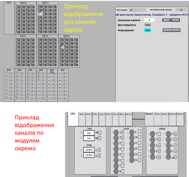
Fig. Example of PLC map display
The classic commissioning method using the buffer pair CH_HMI and CH_BUF remains valid and unchanged. This section describes additional objects (modules and submodules) designed to reduce SCADA/HMI and communication resource usage.
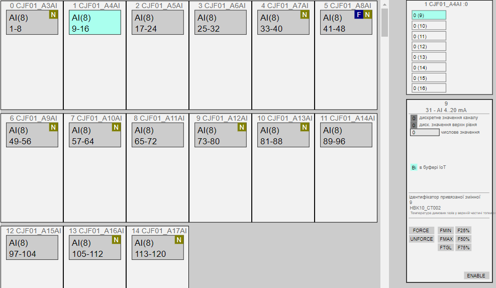
Below is a variant implementation for working with channel groups. Implemented functions include:
- Continuous monitoring (display) of channel errors (at least one) on modules.
- Selecting a channel group for display (“submodule” - a group of 16 channels).
- Displaying the status of channels in the selected group based on
CH_HMIdata. - Loading any channel from the group into the buffer.
- Operating the channel through the buffer (forcing, value changes).
Module Class Structure and MODULES Variables
Ideally, a MODULE represents a physical PLC module that may have up to 4 channel groups represented as Submodules. Each submodule has a position within the module (1 to 4) and can contain up to 16 channels of a single type (AI, DI, AO, DO, COM, etc.), with the submodule type matching the channel type it handles. Submodules within a module can differ in type, allowing the module to hold up to 64 channels of various types (up to 4 submodules with 16 or fewer channels each). This module-submodule structure allows different channel combinations, such as 16DI+16DO+16AI+16AO, or 64DI, etc.
If the PLC architecture physically allows modules with more channels or more submodule types, the framework should represent these using multiple modules. Alternatively, the structures below can be modified, but that goes beyond the framework’s scope.
For ease of maintenance, the framework allows empty modules (placeholders) that contain at least one placeholder submodule in the first position (with other submodules absent).
Module Type:
| name | type | adr | bit | description |
|---|---|---|---|---|
| STA | INT | 0 | module state/command for HMI: xxxx_xxxx_xxxx_1111 - lower 4 bits indicate BAD status of specific submodules; xxxx_xxxx_1111_xxxx - specific submodule in the buffer; xxxx_1111_xxxx_xxxx - command to load a specific submodule into the buffer; 1111_xxxx_xxxx_xxxx - specific submodule in the IoT buffer (for IoT solutions only); | |
| TYPE | UINT | 1 | Submodule types, hexadecimal combination - 1 (16#XYZQ where X is for the first submodule): 0 - absent, 1 - DICH, 2 - DOCH, 3 - AICH, 4 - AOCH, 5 - COM, 6 - NDICH, 7 - NDOCH, 8 - NAICH, 9 - NAOCH, E - other module, F - placeholder module |
|
| CHCNTS | UINT | 2 | number of channels per Submodule, hexadecimal combination - 1 (16#XYZQ where X is for the first submodule). Add 1: if the channel count = 6, the module type will be 5. 0 or 1 channels will display as 0, but a module with 1 channel will have a type, while a module with no channels will have subtype 0 (absent) or F (placeholder). |
|
| STA2 | INT | 3 | additional module states for HMI: xxxx_xxxx_xxxx_1111 - lower 4 bits indicate FRC status of at least one channel in each submodule; xxxx_xxxx_1111_xxxx - presence of at least one free (unused) channel in each submodule; | |
| STRTNMB | ARRAY[0..3] of UINT | 4 | starting channel number for displaying each submodule |
The total number of modules is set in the variable PLCCFG.MODULSCNT. All modules are contained within the MODULES array
Structure of the SUBMODULE class and variable
General information about submodules is contained within the MODULE structure, but to work with a specific group of channels, a separate buffer variable SUBMODULE is used, which serves for displaying (mapping) a group of channels. The submodule shows the state of all channels within that submodule. Further work with channels is performed using the standard framework interaction scheme CH_HMI <-> CH_BUF.
Type SUBMODULE:
| name | type | adr | bit | descr |
|---|---|---|---|---|
| STRTNMB | INT | 0 | starting channel number for displaying the specific submodule | |
| CNT | INT | 1 | number of channels (depends on the module), up to 16 | |
| TYPE | INT | 2 | channel type (0-none, 1-DICH, 2-DOCH, 3-AICH, 4-AOCH, 5-COM, 6-NDICH, 7-NDOCH, 8-NAICH, 9-NAOCH, E-other, F-dummy) | |
| CMD | INT | 3 | command: 1..16 - channel number to load into the buffer | |
| CH | ARRAY [0 to 15] of CHHMI | 4 | values according to the CH_HMI structure |
Function Requirements
To implement work with modules and submodules, two functions are used:
- PLCMAPS – fills the
MODULESarray with the appropriate information, called as needed (e.g., on PLC startup). It may be absent; in that case, the relevant variables must be filled in another way. - MODULS – implements the
MODULE/SUBMODULEfunctionality.
PLCMAPS
- may be a parameterless function or a section,
- sets the
PLCCFGparameters:PLCCFG.DICNTPLCCFG.DOCNTPLCCFG.AICNTPLCCFG.AOCNTPLCCFG.MODULSCNT
- should be executed at PLC startup,
- sets the parameters for each module in the
MODULESarray:MODULES[i].TYPE– 1-DICH, 2-DOCH, 3-AICH, 4-AOCH, 5-COM, etc.MODULES[i].CHCNTS– the number of channels per submodule, hexadecimal combinationMODULES[i].STRTNMB[j]– for submodules that exist (MODULES[i].TYPE<>0)
- upon startup, a submodule should be loaded into the
SUBMODULEbuffer for initial mapping.
Example for TIA Portal
You can request an example initialization block for TIA Portal to fill MODULES, PLCCFG, and load an initial SUBMODULE for visual PLC MAP monitoring if you need it next for structured learning or implementation.
"SYS".PLCCFG.DICNT := 32; // total number of DI channels
"SYS".PLCCFG.DOCNT := 32; // total number of DO channels
"SYS".PLCCFG.AICNT := 10; // total number of AI channels
"SYS".PLCCFG.AOCNT := 6;  // total number of AO channels
"SYS".PLCCFG.MODULSCNT := 5; // total number of MODULES in the system

"HMI".MODULES[0].STA.%X11 := true; // mark submodule 4 as selected for display

// CPU module: DI(1..14), AI(1..2), DO(1..10), AO(1..2)
"HMI".MODULES[0].TYPE := 16#1324; // 1-DICH, 2-DOCH, 3-AICH, 4-AOCH
"HMI".MODULES[0].CHCNTS := 16#D191; // number of channels per submodule, hexadecimal format (16#XYZQ)
"HMI".MODULES[0].STRTNMB[0] := 1;   // starting channel for submodule 1
"HMI".MODULES[0].STRTNMB[1] := 1;   // starting channel for submodule 2
"HMI".MODULES[0].STRTNMB[2] := 1;   // starting channel for submodule 3
"HMI".MODULES[0].STRTNMB[3] := 1;   // starting channel for submodule 4

// DI16 module: DI(17..32)
"HMI".MODULES[1].TYPE := 16#1000;   // submodule type: DICH
"HMI".MODULES[1].CHCNTS := 16#F000; // 16 channels on submodule 1
"HMI".MODULES[1].STRTNMB[0] := 17;  // starting channel at 17

// DO16 module: DO(17..32)
"HMI".MODULES[2].TYPE := 16#2000;   // submodule type: DOCH
"HMI".MODULES[2].CHCNTS := 16#F000; // 16 channels on submodule 1
"HMI".MODULES[2].STRTNMB[0] := 17;  // starting channel at 17

// AI8 module: AI(3..10)
"HMI".MODULES[3].TYPE := 16#3000;   // submodule type: AICH
"HMI".MODULES[3].CHCNTS := 16#7000; // 8 channels on submodule 1
"HMI".MODULES[3].STRTNMB[0] := 3;   // starting channel at 3

// AQ4 module: AQ(3..6)
"HMI".MODULES[4].TYPE := 16#4000;   // submodule type: AOCH
"HMI".MODULES[4].CHCNTS := 16#3000; // 4 channels on submodule 1
"HMI".MODULES[4].STRTNMB[0] := 3;   // starting channel at 3
MODULS Function
- may be a parameterless function or a section,
- must monitor buffer transfer commands to
SUBMODULEfromModules[].STA:- load into the
SUBMODULEbuffer: the number of channels, channel type, and starting channel number,
- load into the
- must update
Modules[].STA, - must ensure work with the
SUBMODULEbuffer:- update
CHaccording to the type and number of channels, - monitor the
CMDcommand for loading into theCHbuffer,
- update
- should be called at the end of the main task.
TIA Portal example available on request for structured implementation.
//loop through all modules
FOR #i := 0 TO "SYS".PLCCFG.MODULSCNT - 1 DO
    #modtype := "DBMODULES".MODULES[#i].TYPE; //module type
    #modchcnts := "DBMODULES".MODULES[#i].CHCNTS; //number of channels in each submodule
    #modSTA := 0; //status
    #modSTA2:=0; //status2
    //iterate through submodules
    FOR #j := 0 TO 3 DO
        #zm := 12 - 4 * #j; //offset for SHIFT
        //submodule type
        #sbmtype := SHR(IN := #modtype, N := #zm) AND 16#000F;
        //number of channels in submodule
        #sbmchcnts:= (SHR(IN := #modchcnts, N := #zm) AND 16#000F) + 1;
        //starting channel index
        #sbmstrtnmb := "DBMODULES".MODULES[#i].STRTNMB[#j];
        //check bit commands
        #mask := 16#0800; //mask for shifting command bit
        #cmdLoadsbm := ("DBMODULES".MODULES[#i].STA AND SHR(IN := #mask, N :=#j))<>0 AND #sbmtype<>0;
        //load submodule into buffer
        IF #cmdLoadsbm THEN
            "BUF".SUBMODULE.TYPE := #sbmtype;
            "BUF".SUBMODULE.CNT := #sbmchcnts;
            "BUF".SUBMODULE.STRTNMB := #sbmstrtnmb;
        END_IF;
        //determine module error by MERR bit of the first channel in the module
        CASE #sbmtype OF
            1:  (*DI*)
                #sbmbad := "CH".CHDI[#sbmstrtnmb].STA.%X6; (*MERR*)
            2:  (*DQ*)
                #sbmbad := "CH".CHDO[#sbmstrtnmb].STA.%X6; (*MERR*)
            3:  (*AI*)
                #sbmbad := "CH".CHAI[#sbmstrtnmb].STA.%X6; (*MERR*)
            4:  (*AO*)
                #sbmbad := "CH".CHAO[#sbmstrtnmb].STA.%X6; (*MERR*)
        END_CASE;
        #mask := 16#0008; //mask for shifting error bit
        IF #sbmbad THEN
            #modSTA := #modSTA OR SHR(IN := #mask, N := #j);
        END_IF;
        //check if this submodule is in the buffer
        #inbuf := #sbmtype<>0 AND ("BUF".SUBMODULE.TYPE = #sbmtype) AND ("BUF".SUBMODULE.STRTNMB = #sbmstrtnmb);
        #mask := 16#0080;
        IF #inbuf THEN
            #modSTA := #modSTA OR SHR(IN := #mask, N := #j);
        END_IF;
        //determine if there is at least one forced channel hasfrc and at least one free channel hasfree 11.10.21
        #hasfrc:=false;
        #hasfree:=false;
        FOR #k := 0 TO #sbmchcnts-1 DO
            CASE #sbmtype OF
                1:  (*DI*)
                    #hasfrc := #hasfrc OR "SYS".CHDI[#sbmstrtnmb + #k].STA.FRC;
                    #hasfree := #hasfree OR NOT "SYS".CHDI[#sbmstrtnmb + #k].STA.ULNK;
                2:  (*DQ*)
                    #hasfrc := #hasfrc OR "SYS".CHDO[#sbmstrtnmb + #k].STA.FRC;
                    #hasfree := #hasfree OR NOT "SYS".CHDO[#sbmstrtnmb + #k].STA.ULNK;
                3:  (*AI*)
                    #hasfrc := #hasfrc OR "SYS".CHAI[#sbmstrtnmb + #k].STA.FRC;
                    #hasfree := #hasfree OR NOT "SYS".CHAI[#sbmstrtnmb + #k].STA.ULNK;
                4:  (*AO*)
                    #hasfrc :=#hasfrc OR "SYS".CHAO[#sbmstrtnmb + #k].STA.FRC;
                    #hasfree := #hasfree OR NOT "SYS".CHAO[#sbmstrtnmb + #k].STA.ULNK;
            END_CASE;
        END_FOR;
        #mask := 16#0008;
        IF #hasfrc THEN
            #modSTA2 := #modSTA2 OR SHR(IN := #mask, N := #j);
        END_IF;
        #mask := 16#0080;
        IF #hasfree THEN
            #modSTA2 := #modSTA2 OR SHR(IN := #mask, N := #j);
        END_IF;

        //work with the submodule in the buffer
        IF #inbuf THEN
            #sbmCMD := "BUF".SUBMODULE.CMD; //command for the submodule
            //check command and load channel values into buffer
            FOR #k := 0 TO #sbmchcnts-1 DO
                #cmdLoadch := #sbmCMD = (#k + 1); //load channel
                CASE #sbmtype OF
                    1:  (*DI*)
                        "CH".CHDI[#sbmstrtnmb + #k].STA.%X15 := #cmdLoadch;
                        "BUF".SUBMODULE.CH[#k] := "CH".CHDI[#sbmstrtnmb + #k];
                    2:  (*DQ*)
                        "CH".CHDO[#sbmstrtnmb + #k].STA.%X15 := #cmdLoadch;
                        "BUF".SUBMODULE.CH[#k] := "CH".CHDO[#sbmstrtnmb + #k];
                    3:  (*AI*)
                        "CH".CHAI[#sbmstrtnmb + #k].STA.%X15 := #cmdLoadch;
                        "BUF".SUBMODULE.CH[#k] := "CH".CHAI[#sbmstrtnmb + #k];
                    4:  (*AO*)
                        "CH".CHAO[#sbmstrtnmb + #k].STA.%X15 := #cmdLoadch;
                        "BUF".SUBMODULE.CH[#k] := "CH".CHAO[#sbmstrtnmb + #k];
                END_CASE;
            END_FOR;
            "BUF".SUBMODULE.CMD := 0;
        END_IF;
    END_FOR;

    //write status to module
    "DBMODULES".MODULES[#i].STA := #modSTA;
    "DBMODULES".MODULES[#i].STA2:= #modSTA2;

END_FOR;

FOR #i := 0 TO 15 DO
    "BUF".SUBMODULE.CH[#i].STA.%X9:="BUF".SUBMODULE.CNT-1<#i;
END_FOR;
MODULES_IOT
Commands from IoT buffer
16#00xx– commands for channels16#01xx– commands for MODULE/SUBMODULE16#0111..0114– load into buffer
Usage for network channels
The same principle is used for network channels, but the logical mapping may differ significantly from the physical one.
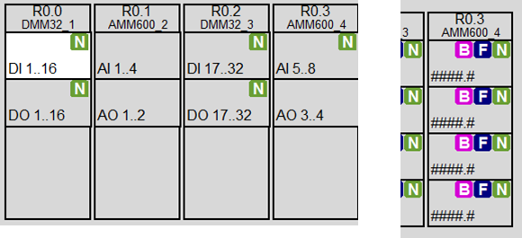
Recommendations for HMI usage
Each submodule should display:
- presence of at least one forced channel in the group
F(white letter on blue background), - presence of at least one channel error
B(white letter on pink background), - presence of free (unlinked) channels
N(white letter on olive background).
Colors and symbols are optional and not part of PACFramework.
Testing
to-do
Test list
- all functions are checked after implementing PLCFN, CH and their instances
| No. | Title | Notes |
|---|---|---|
| 1 | Modules initialization | performed on first scan |
| 2 | Test loading required submodule into SUBMODULE buffer | performed after function implementation |
| 3 | Loading required channel into CH_BUF buffer | performed after function implementation |
| 4 | Transfer of forced channel information to MODULE variable | performed after function implementation |
| 5 | Transfer of channel and module error information | performed after function implementation |
| 6 | Transfer of information about free and linked channels | performed after function implementation |
1 Modules initialization
- PLC must be in STOP before testing
- after PLC startup:
- MODULES should be filled with appropriate values,
- SUBMODULE buffer should be filled with one of the submodules (typically the first module with I/O).
2 Test loading required submodule into SUBMODULE buffer
| Step | Action | Result |
|---|---|---|
| 1 | Change the load command bit of an existing module and submodule | Load bit in buffer should change, SUBMODULE buffer should load the corresponding submodule with: STRTNMBCNTTYPE |
| 2 | Repeat step 1 for another module and/or submodule | Load bit in buffer should change, SUBMODULE buffer should load the corresponding submodule with: STRTNMBCNTTYPE |
3 Loading required channel into CH_BUF buffer
| Step | Action | Result |
|---|---|---|
| 1 | Write the channel number to BUF_SUBMODULE.CMD, e.g., 1 |
The full content of CH_CFG should load into CHBUF. For CH_HMI, CH_CFG, CH_BUF, and BUF.SUBMODULE.CH[0].STA, the bit STA.12(INBUF) should be 1 |
| 2 | Change a variable value (e.g., for DICH – input RAW) | The value should change in CH_HMI, CH_CFG, CH_BUF, and BUF.SUBMODULE.CH[0].STA |
| 3 | Repeat steps 1 and 2 for another channel | The full content of CH_CFG of another variable should load into CHBUF |
4 Transfer of forced channel information to MODULE variable
| Step | Action | Result |
|---|---|---|
| 1 | Load any channel into CH_BUF buffer |
The full content of CH_CFG should load into CHBUF |
| 2 | Send the force command CHBUF.CMD=16#0301 |
The forced bit FRC of the selected channel should be 1.The corresponding bit (0-3 depending on the submodule) in MODULE.STA2 should be 1 according to the channel’s submodule |
| 3 | Load another channel into CH_BUF buffer |
The full content of CH_CFG should load into CHBUF |
| 4 | Send the force command CHBUF.CMD=16#0301 again |
The forced bit FRC of the selected channel should be 1.The corresponding bit in MODULE.STA2 should be 1 according to the channel’s submodule |
| 5 | De-force all objects with command "SYS".PLCCFG.CMD=16#4302 |
All FRC bits should become 0.The corresponding bit (0-3 depending on the submodule) in MODULE.STA2 should also become 0 |
5 Transfer of channel and module error information
| Step | Action | Result |
|---|---|---|
| 1 | Set CH_CFG.STA.BAD to 1 for any channel |
The corresponding bit (0-3 depending on the submodule) in MODULE.STA should be 1 according to the channel’s submodule |
| 2 | Set CH_CFG.STA.BAD to 0 for the selected channel |
The corresponding bit in MODULE.STA should become 0 |
| 3 | Repeat for another channel | Same result as above |
6 Transmission of Information About Free and Linked Channels
- Immediately after startup, all channels will be unlinked –
CHBUF.STA.ULNKequals 0. - To start the test, a variable such as
TST_HASFREEis used. - The channel number is set via test variables
TST_CHDI_ID1..TST_CHDI_ID16. - After calling the channel handler functions, a test function is called where the
CH_CFG.PNGgroup values are modified, similar to a ping-pong test:
IF TST_HASFREE THEN
    CHDI[TST_CHDI_ID1].STA.PNG := true;
    CHDI[TST_CHDI_ID1].VARID := TST_CHDI_ID;
    CHDI[TST_CHDI_ID2].STA.PNG := true;
    CHDI[TST_CHDI_ID2].VARID := TST_CHDI_ID;
    ...
    CHDI[TST_CHDI_ID16].STA.PNG := true;
    CHDI[TST_CHDI_ID16].VARID := TST_CHDI_ID;
END_IF;
| Step | Action for Verification | Expected Result |
|---|---|---|
| 1 | Do nothing | The corresponding bit (bits 4–7 depending on the submodule) of the MODULE.STA2 variable, depending on which submodule the channels belong to, should be set to 1. |
| 2 | Set the values of TST_CHDI_ID1..TST_CHDI_ID16 within the range of existing channels and set TST_HASFREE=TRUE. |
For the specified variables: CH_CFG.VARID should equal the specified value, and CH_CFG.ULNK=TRUE. The corresponding bit (bits 4–7 depending on the submodule) of the MODULE.STA2 variable, depending on which submodule the channels belong to, should be set to 0. |
| 3 | Change one of the channels, for example: CHDI[TST_CHDI_ID16].STA.PNG := false; |
The channel should reset CH_CFG.VARID and CH_CFG.ULNK. The corresponding bit (bits 4–7 depending on the submodule) of the MODULE.STA2 variable, depending on which submodule the channels belong to, should be set back to 1, indicating a free unlinked channel in the submodule is present. |