PACFramework
LVL0 Classes
(CLSID = 16#000x – 16#07FF)
General Description
The lowest level of control modules (channels) provides abstraction from specific hardware (PLC, distributed I/O, etc.). The implementation of this level depends on both the selected platform and the implementation approach. CM elements of the “channel” type represent arrays of all available controller channels, regardless of their location (local rack, remote I/O) or whether they are actively used in the process. Each array element is identified by a unique number, and the binding to the physical channel is strictly implemented at the software level. Channel-type CMs bind their values to the physical value of a specific channel and perform the following functions:
- Provide diagnostic information to higher-level CMs, at minimum indicating data validity, and when possible, the reason for channel fault/error.
- Support forced value modes:
- Forced change of input channel value regardless of physical input.
- Forced change of output channel value regardless of the value provided by the variable.
- Show the link status to a process variable and the variable’s ID.
Within the framework, channels are represented by five base classes:
- CHDI (CLSID=16#001x) – digital input channels
- CHDO (CLSID=16#002x) – digital output channels
- CHAI (CLSID=16#003x) – analog input channels
- CHAO (CLSID=16#004x) – analog output channels
- CHCOM (CLSID=16#005x) – communication channels (general)
Additionally, network channels can be used when dynamic binding of process variables to channels is required. Network channels are processed by the same functions as base channels, with the raw value sourced from the communication exchange variable. This approach allows runtime switching from a network channel to a local channel without changes to the process variable or program structure.
- CHNDI (CLSID = 16#006x) – digital input network channels
- CHNDO (CLSID = 16#007x) – digital output network channels
- CHNAI (CLSID = 16#008x) – analog input network channels
- CHNAO (CLSID = 16#009x) – analog output network channels
The last digit further specifies the class. Recommended class number usage is provided in each specific class description.
HMI Usage Recommendations
Mimic diagrams displaying channel status within the framework are called PLC Maps. These maps provide functions to display linked channels, validity indication, and forcing commands. Channels are highlighted in the event of hardware errors.
To optimize variable usage, it is recommended to:
- Use a single buffer variable
CH_BUFfor all channels. - Use the MODULES class.
For HMI, it is essential to implement PLC maps displaying channel statuses (values, variable usage, channel errors) even if not used in all cases. Forcing outputs or quickly identifying which variable uses a channel is often required. A simple approach is to display a shortened CH_HMI structure in the HMI, but the tag count for large PLC systems becomes significant. A practical alternative is grouping channel information by 16 or by modules for display. Examples are shown in Fig. 2.5, implemented using the MODULES class.
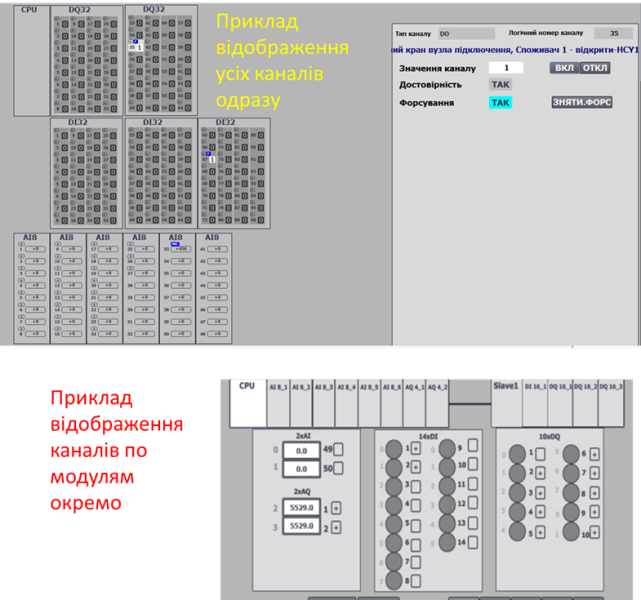
Fig. 2.5. Example PLC map display
Structure of CHDI/CHDO/CHAI/CHAO Classes
The class structure is used for variables of all channels. Channels with CLSID = 16#00x0 are intended for channels without specific diagnostics; all others depend on the module type and may include additional diagnostic bits.
CH_CFG Structure
adr indicates the offset in the structure in 16-bit words.
| name | type | adr | bit | descr |
|---|---|---|---|---|
| ID | UINT | 0 | Unique identifier - variable number. The number of available channels equals the highest number. Numbering is logical and defined during project design. ID = 0 is reserved for error operations; real channels are numbered starting from 1. |
|
| CLSID | UINT | 1 | - CHDI (CLSID=16#001x): digital input channels- CHDO (CLSID=16#002x): digital output channels- CHAI (CLSID=16#003x): analog input channels- CHAO (CLSID=16#004x): analog output channels |
|
| STA | UINT | 2 | May be a CH_STA bit set |
|
| VRAW | BOOL | 2 | 0 | For digital signals:- CHDI: value from digital input- CHDO: value to digital output- In FRC=1 mode, can be modified externally for CHDO- CHAI: RAWINT>0- CHAO: RAWINT>0 |
| VALB | BOOL | 2 | 1 | Digital signal value for higher-level CM:- CHDI: read by DIVAR- CHDO: written by DOVAR- In FRC=1 mode, can be modified externally for CHDI- CHAI: CHCFG.VAL>0- CHAO: CHCFG.VAL>0 |
| BAD | BOOL | 2 | 2 | =1 – channel fault (BRK, SHRT, or other) |
| b3 | BOOL | 2 | 3 | reserved |
| PNG | BOOL | 2 | 4 | =1 – PING request received from owner, cleared by channel (PONG response) |
| ULNK | BOOL | 2 | 5 | =1 – channel used by a process variable (linked) DIVAR/AIVAR/DOVAR/AOVAR |
| MERR | BOOL | 2 | 6 | =1 – module-wide error (diagnostic information) |
| BRK | BOOL | 2 | 7 | =1 – channel break fault |
| SHRT | BOOL | 2 | 8 | =1 – short circuit or overload fault |
| NBD | BOOL | 2 | 9 | =1 – channel does not physically exist; used for HMI visualization in MODULS buffer or when non-existent channels simplify addressing alignment |
| b10 | BOOL | 2 | 10 | reserved |
| INIOTBUF | BOOL | 2 | 11 | =1 – CH variable loaded into IoT buffer CH_BUF |
| INBUF | BOOL | 2 | 12 | =1 – CH variable loaded into buffer CH_BUF |
| FRC | BOOL | 2 | 13 | =1 – value is forced |
| SML | BOOL | 2 | 14 | =1 – value is simulated (by higher level) |
| CMDLOAD | BOOL | 2 | 15 | =1 – request to load into buffer (HMI only) |
| CMD | UINT | 3 | Command:- 16#0001: write 1/MAX- 16#0002: write 0/MIN- 16#0003: toggle 0<->1 for digital, set to MID for analog- 16#0100: read configuration to buffer- 16#0300: toggle forcing- 16#0301: enable forcing- 16#0302: disable forcing | |
| VAL | INT | 4 | Value:- CHAI: analog input value for AIVAR- CHAO: analog output value from AOVAR- CHDI = STA.VAL- CHDO = STA.VAL |
|
| VARID | UINT | 5 | ID of the linked process variable, 0 if unlinked |
CH_HMI Structure
| name | type | adr | bit | descr |
|---|---|---|---|---|
| STA | INT | 0 | STA + CMD (bit X15 = CMDLOAD for loading into buffer) |
|
| VAL | INT | 1 | Value from CH_CFG.VAL |
CH_BUF Variable
The CH_BUF type follows the same general structure as CH_CFG. However, when using bit fields within the STA structure, the fields should be converted to INT for consistency.
General Requirements for CH Functions
Functional Requirements
- Channel identification (ID) must be unique within each class. The total number of available channels is determined by the highest assigned number. Numbering is logical and defined during project development.
ID = 0is reserved for error operations; real channels are numbered starting from 1. - The following commands must be monitored and implemented:
- Personal command from HMI:
STA.CMDLOAD - Commands:
- 16#0001 – write
TRUE(only when forcingCHDI/CHDO) - 16#0002 – write
FALSE(only when forcingCHDI/CHDO) - 16#0003 –
TOGGLE– invert the current value (only when forcingCHDI/CHDO) - 16#0100 – read configuration into the buffer (link to buffer)
- 16#0001 – write
- Broadcast PLC commands:
- Unforce all channels: 16#4302
- Personal command from HMI:
- A buffer management function must be implemented:
- A single buffer is recommended for all channels (except possibly
CHCOM). - Buffer occupancy is checked by matching
CLSIDandID. - Channel configuration should be read into the buffer upon receiving:
- Status bit
STA.CMDLOAD = TRUE CFG.CMD = 16#0100
- Status bit
- Upon buffer acquisition:
CH_BUF.STA = CH_CFG.STACH_CFG.CMD = CH_BUF.CMDif not zero (allowing commands from other sources)- In force mode:
CH_CFG.VAL = CH_BUF.VAL - In normal mode:
CH_BUF.VAL = CH_CFG.VAL
- A single buffer is recommended for all channels (except possibly
- The channel must participate in binding to a process variable:
- Binding status is managed using the PING-PONG algorithm (see below).
VARIDindicates the ID of the variable linked to the channel.- Control and management of binding are handled by process variables (xxVAR).
- Support for two modes: forced and normal (non-forced):
- Force mode status must reflect in the general status bit
FRC. - In normal mode:
CHDI,CHAI: the value for the process variable is taken from theRAWinput.CHDO,CHAO: theRAWoutput value is taken from the linked output process variable.
- In forced mode:
CHDI,CHAI: the linked input process variable (AIVAR,DIVAR) should receive the forced value fromCH_BUF.VALif the channel is in the buffer; otherwise, it retains the previous value.CHDO,CHAO: theRAWoutput should receive the forced value fromCH_BUF.VALinstead of the process variable if the channel is in the buffer; otherwise, it retains the previous value.- The global variable
PLC_CFG.CNTFRCshould increment by 1.
- Force mode status must reflect in the general status bit
- At least the quality bit
CHCFG.BADshould update according to the channel state. Other bits can be implemented as needed.
Interface Implementation Requirements
- IN:
CHDI: value from the controller’s digital inputs (RAW)CHAI: value from the controller’s analog inputs (RAWINT)
- INOUT:
CHDO: value to the controller’s digital outputs (RAW)CHAO: value to the controller’s analog outputs (RAWINT) (must link to an actual variable)CHCFGCHHMI- If internal functions cannot access external variables,
PLC_CFGshould be passed; alternatively, other interfaces withinPLC_CFGcan be used.
User Program Implementation Requirements
- Channel processing functions must be called in every cycle of the task they are linked to.
- On first startup (
PLC_CFG.SCN1), the channel counts should be initialized:
PLCFN1(PLC_CFG);
IF PLC_CFG.STA.SCN1 THEN
    PLC.DICNT := 32;
    PLC.DOCNT := 32;
    PLC.AICNT := 10;
    PLC.AOCNT := 6;
END_IF;
- The POU calling channel processing functions should contain an initialization condition on first startup using
PLC_CFG.SCN1, during which:- Variables are assigned default IDs and classes if they are zero.
- Channels used for address alignment (non-existent channels) should have
STA.NBD = TRUE.
PING-PONG Algorithm
The framework supports flexible binding of process variables to channels. For easy identification of available channels on the PLC map, each channel should monitor its binding status (usage) and know which variable is using it. Binding status is indicated by the ULNK (Uplink) bit.
This bit inherits the PNG (Ping request) bit at the start of the CH_FN function, after which PNG is reset to FALSE (Pong response). The process variable (owner) using the channel sets CH_CFG.STA.PNG := TRUE on each call of VAR_FN and assigns its ID to CH_CFG.VARID := VAR_CFG.ID.
Thus, if no variable claims the channel, the PNG value, and subsequently the ULNK value, for the channel will become FALSE. This mechanism is referred to as the “Ping-Pong” algorithm.
Testing CHx_FN
This section describes the manual and/or automated testing methodology for functions typical for all CHDIFN, CHAIFN, CHDOFN, and CHAOFN.
Test List
| No. | Name | When to test | Notes |
|---|---|---|---|
| 1 | ID and CLSID assignment at startup | After function implementation | |
| 2 | Buffer binding commands | After function implementation | |
| 3 | Operation in non-forced mode | After function implementation | |
| 4 | Operation in forced mode | After function implementation | |
| 5 | Ping-Pong | ||
| 6 | Sending broadcast force/unforce commands | ||
| 7 | Simulation mode check | ||
| 8 |
1. ID and CLSID Assignment at Startup
- Before testing, the PLC should be in STOP.
- After startup, all channels used in the program should receive assigned IDs and CLSIDs.
2. Buffer Binding Commands
| Step | Action | Expected Result | Notes |
|---|---|---|---|
| 1 | Set STA.X15 = 1 for one of the CH_HMI variables |
The entire CH_CFG content should load into CHBUF. CH_HMI should reset STA.X15 = 0.STA.12 (INBUF) should be 1 in CH_HMI, CH_CFG, and CHBUF. |
|
| 2 | Change a variable value (e.g., DICH input RAW) |
The corresponding value updates in CH_HMI, CH_CFG, and CHBUF. |
|
| 3 | Set STA.X15 = 1 for another CH_HMI variable |
The CH_CFG content of the other variable should load into CHBUF. |
|
| 4 | Repeat step 1 using CH_CFG.CMD = 16#100 |
Same as step 1; after loading, CH_CFG.CMD should reset to 0. |
3. Operation in Non-Forced Mode
Tests should verify values in CH_HMI, CH_CFG, and CH_BUF.
| Step | Action | Expected Result | Notes |
|---|---|---|---|
| 1 | Bind a test variable to the buffer | The entire CH_CFG content should load into CHBUF. |
|
| 2 | Change variable value (e.g., DICH input RAW) |
Live and raw values should update in CH_HMI, CH_CFG, and CH_BUF (for CHDI and CHDO). |
See class-specific tests |
| 3 | Repeat step 2 with a different value |
4. Operation in Forced Mode
Tests should verify values in CH_HMI, CH_CFG, and CH_BUF.
| Step | Action | Expected Result | Notes |
|---|---|---|---|
| 1 | Bind a test variable to the buffer | The entire CH_CFG content should load into CHBUF. |
|
| 2 | Change input value to 0 |
Value changes as in Test 3. | Input: RAW for DICH, AICH; VAL for DOCH, AOCH. |
| 3 | Send force command CHBUF.CMD = 16#0301 |
FRC bit should be 1. |
|
| 4 | Change input value | Output value should remain unchanged. | Same as step 2. |
| 5 | Send command 16#0001 (write 1/MAX) |
Value changes to 1/MAX. |
|
| 6 | Send command 16#0002 (write 0/MIN) |
Value changes to 0/MIN. |
|
| 7 | Send command 16#0003 (TOGGLE/set to mid-range) |
Value toggles or sets to mid-range. | |
| 8 | Change CHBUF.VAL |
Value changes to the specified value (>0 → 1 for digital). |
|
| 9 | Send unforce command CHBUF.CMD = 16#0302 |
FRC bit should reset to 0. |
|
| 10 | Send toggle force command 16#0300 repeatedly, ending in force mode |
FRC bit should toggle accordingly. |
|
| 11 | Force multiple variables | FRC bit of those variables should be 1. |
|
| 12 | Check PLC.STA_PERM and PLC.CNTFRC_PERM values |
PLC.STA_PERM.X13 = 1; PLC.CNTFRC_PERM equals the number of forced variables. |
|
| 13 | Unforce all variables | PLC.STA_PERM.X13 = 0; PLC.CNTFRC_PERM = 0. |
5. Ping-Pong Check
- Use a test variable, e.g.,
TST_CHDIPNGONforCHDI. - Set the channel number using
TST_CHDIPNGID. - After calling the channel handler functions, call the test function to modify
CH_CFG.PNG:
IF TST_CHDIPNGON THEN
    CHDI[TST_CHDIPNGID].STA.PNG := true;
    CHDI[TST_CHDIPNGID].VARID := TST_CHDIPNGID;
END_IF;
| Step | Action | Expected Result | Notes |
|---|---|---|---|
| 1 | Write a value to CH_CFG.VARID |
Should reset, as the variable is unlinked. | |
| 2 | Set TST_CHDIPNGID to a valid channel, TST_CHDIPNGON = TRUE |
CH_CFG.VARID and CH_CFG.ULNK should reflect the set value and show TRUE. |
|
| 3 | Change TST_CHDIPNGID to another valid channel, TST_CHDIPNGON = TRUE |
Previous channel resets CH_CFG.VARID and ULNK, new channel shows values as in step 2. |
|
| 4 | Set TST_CHDIPNGON = FALSE |
Previous channel resets CH_CFG.VARID and ULNK. |
6. Sending Broadcast Force/Unforce Commands
| Step | Action | Expected Result | Notes |
|---|---|---|---|
| 1 | Send broadcast force command PLC.CMD = 16#4301 |
FRC bit of all variables becomes 1, PLC.CNTFRC_PERM equals the number of variables. |
|
| 2 | Send broadcast unforce command PLC.CMD = 16#4302 |
FRC bit of all variables becomes 0, PLC.CNTFRC_PERM = 0. |