PACFramework
LVL1 Classes
CLSID = 16#100x – 16#17FF
General Description
LVL1 (process variables) are technological variables for complete process data handling, including channel linking, filtering, scaling, inversion, etc.; simplifying process debugging; simulation functions; process alarming functions, and more.
It is recommended to use consistent identification (ID) of process variables within LVL1 to simplify symbolic referencing in the HMI.
The process variable level is represented by four classes:
- DIVAR (CLSID=16#101x) – discrete process input variables,
- DOVAR (CLSID=16#102x) – discrete process output variables,
- AIVAR (CLSID=16#103x) – analog process input variables,
- AOVAR (CLSID=16#104x) – analog process output variables,
If needed, separate classes for network variables can be defined. It is recommended to process network variables using the same functions as standard technological variables.
- NDIVAR (CLSID = 16#105x) – network discrete process input variables
- NDOVAR (CLSID = 16#106x) – network discrete process output variables
- NAIVAR (CLSID = 16#107x) – network analog process input variables
- NAOVAR (CLSID = 16#108x) – network analog process output variables
A single buffer with the structure VARBUF is used.
A variable with ID = 0 is reserved as an empty, inactive variable.
HMI Usage Recommendations
An example of diagnostics and configuration of analog variables on the HMI is shown below. Windows displaying the list of all process variables within the framework are referred to as process variable maps.
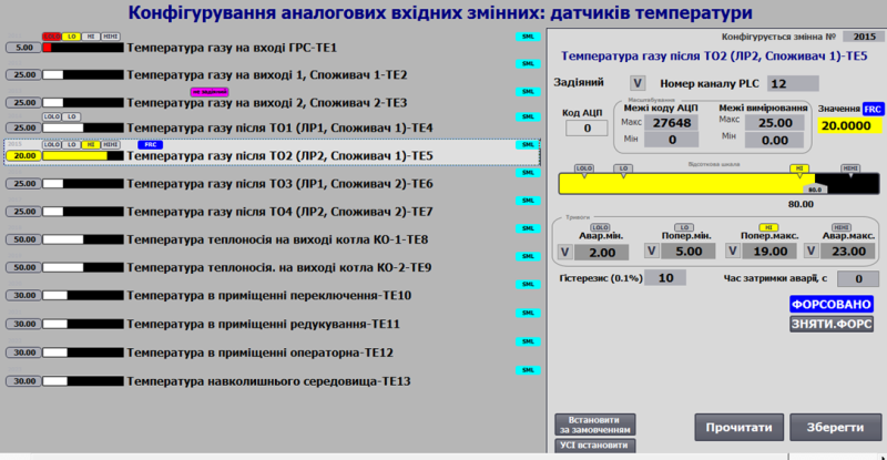
Fig. Example of using analog input variable functions on the HMI.
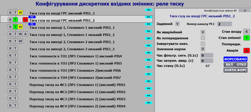
Fig. Example of configuring discrete input variable functions on the HMI.
Variable statuses (alarms, faults, forced state) accompany the display of variables on all HMI mimic diagrams. The following image shows an example of warning display for variable PT102 on a panel with limited functionality (Simatic Basic Panel).
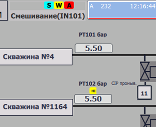
Fig. Example of displaying variable status on the HMI.
General Requirements for Variable Class Structures
The structures must contain:
| Name | Type | Description |
|---|---|---|
| ID | UINT | Unique identifier |
| CLSID | UINT | 16#10xx |
| STA | INT | Status bits |
| PRM | UINT | Configuration parameters, must be retained after power-off |
| CHID | UINT | Logical channel number to which the variable is linked, 0 = not linked |
| CHIDDF | UINT | Default logical channel number |
| prm1 | Parameters according to the technological variable class | |
| prm2 | Parameters according to the technological variable class | |
| prm3 | Parameters according to the technological variable class | |
| STEP1 | UINT | Step number |
| T_STEP1 | UDINT | Elapsed step time in ms |
| T_PREV | UDINT | Time in ms since the previous call, taken from PLC_CFG.TQMS |
General Requirements for VAR Functions
Functional Requirements
Level 1 CMs (process variables) can be linked to a channel of the same type (e.g., a discrete input to a discrete input process variable) by their number. This allows dynamic linking of a process variable to a channel, enabling physical reallocation of a specific sensor/actuator in case part of the system fails. Additionally, this switching can be done programmatically.
Process variables are higher in the control hierarchy than channels. All diagnostic information is transmitted from the channels to the variables. The implementation of this level is hardware-independent since all platform-specific details are handled at the channel level, whose interface is standardized within the framework.
Process variables provide the following functionalities:
- Linking to a channel by its number and type.
- Taking out of service (deactivation of variable alarms, recognized by higher levels).
- Monitoring value validity via errors from the linked channel, exceeding measurement range, etc.
- Channel diagnostics (transferring diagnostic information from the linked channel to higher levels).
- Input/output value handling: scaling (including piecewise linear interpolation if needed), filtering, inversion (for discrete variables).
- Manual change mode (forcing), according to ISA-88 “manual mode”.
- Simulation mode, where input variables can have their values set by higher-level CMs (or independent programs), while output variable values are frozen at the output channels.
- Alarm handling (ISA 18.2): threshold triggering, activation delay (thresholds can be set separately), hysteresis, setting system-wide alarm/warning bits, generating “new alarm” (single cycle).
- Alarm processing configuration (ISA 18.2): setting alarm values, alarm types (alarm/warning/channel failure), temporarily disabling alarms.
- Support for simulation mode.
Working with the Buffer
A classic buffer handling function must be implemented.
- It is recommended to use a single buffer for all process variables.
- Buffer occupancy is checked by matching the
CLSIDandIDof the process variable. - When the buffer is captured:
VARBUF.STA = VAR_CFG.STAIVAR_CFG.CMD = VARBUF.CMDif it is not zero (to allow commands from other sources)- Reading the status bits of the physical channel linked to the process variable:
VARBUF.CH_STA = CHCFG.STA.
- Configuration of the process variable should be read into the buffer when receiving commands:
- When status bit
STA.CMDLOAD = TRUE - When the variable is already in the buffer and
VARBUF.CMD = 16#0100
- When status bit
- Configuration of the process variable should be written from the buffer upon receiving commands:
- When
VARBUF.CMD = 16#0101
- When
A function for bidirectional buffer handling (VARBUFIN <-> VARBUFOUT) should be implemented.
- Two buffers are used:
- Input buffer
VARBUFIN: used for processing commands (whenCLSIDandIDmatch) and writing information into the process variable. - Output buffer
VARBUFOUT: used for reading information from the process variable upon receiving a read command inVARBUFIN.
- Input buffer
- It is recommended to use a single pair of buffers for all process variables.
- Buffer occupancy is not applicable since it is implemented using two buffer variables (VARBUFIN and VARBUFOUT), through which data is passed for further transfer to the process variable or to the internal HMI buffer (similar to PKW parameter exchange in PROFIDRIVE profiles).
- Process variable configuration should be read into the output buffer when:
VARCFG.CLSID = VARBUFIN.CLSID,VARCFG.ID = VARBUFIN.ID, andVARBUFIN.CMD = 16#100
- Process variable configuration should be written from the input buffer when:
VARCFG.CLSID = VARBUFIN.CLSID,VARCFG.ID = VARBUFIN.ID, andVARBUFIN.CMD = 16#101
Interface Requirements
The interface should pass the following parameters:
- xxVARCFG - INOUT
- xxVARHMI - INOUT
- CHCFG - INOUT
If direct access to external variables from inside functions is not possible, PLC_CFG, VARBUF, VARBUFIN, and VARBUFOUT should be passed. Alternatively, other interfaces may be used to access PLC_CFG internally.
User Program Implementation Requirements
Within the general program (outside the class function implementation):
- On first startup:
- Initialize variable identifiers (ID).
- Have a variable occupy the buffer.
- Handle conflicts when a variable attempts to occupy a channel already occupied by another variable via buffer handling.
Within the class function implementation:
- On first startup:
- Initialize variable classes (CLSID).
- Write default CHID (channel ID) values if
CHID = 0. - Set
PRM_DSBL := FALSE. - Set
T_PREV := PLC_CFG.TQMS. - Set
T_STEP1 := 0.
- Write CHID (channel ID) values by default upon receiving the corresponding command.
Testing
General Test List
| No. | Name | When to check | Notes |
|---|---|---|---|
| 1 | Assigning ID and CLSID on startup | After function implementation | |
| 2 | Buffer write commands | After function implementation | |
| 3 | Parameter modification and writing from the buffer | After function implementation | |
| 4 | Changing the logical channel number | After function implementation | |
| 5 | Writing CHID values by default on startup or single command | After function implementation | |
| 6 | Operation of built-in time counters | After function implementation | |
| 7 | Effect of PLC time counter overflow on step time | After function implementation | |
| 8 | Ping-Pong algorithm | After function implementation | |
| 9 | Operation in non-forced mode | After function implementation | |
| 10 | Operation in forced mode | After function implementation | |
| 11 | Sending broadcast commands to clear forcing | After function implementation |