PACFramework
Program for Simulating an Installation with Dosing Vessels
General Description of the Simulated Installation
To create and test library blocks, you can use an object simulator that can be deployed on the same PLC, a PLC emulator where the framework is deployed, or as external software. The simulated installation is shown in Fig. 1.
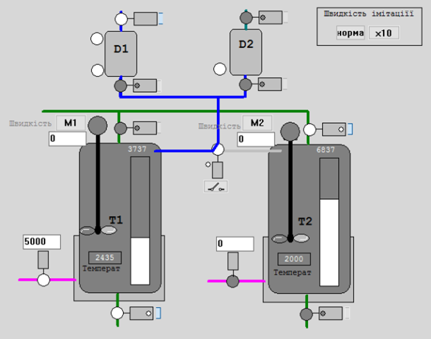
Fig. 1. Image of the simulated installation for testing PACFramework blocks.
The process preparation installation consists of the following elements (Fig. 1):
- Tanks T1 and T2, in which products are prepared according to different recipes; the tanks are equipped with the following instrumentation and control devices:
- inlet and outlet shut-off valves, each with “closed” and “open” limit switches;
- a control valve (0-100%, shown in PLC units as 0-10000) for supplying the heating medium to the tank’s heat exchange jacket (hereafter referred to as the heating valve);
- a level sensor (0-100%, shown in PLC units as 0-10000) in the tank;
- a temperature sensor in the tank (0-100°C, shown in PLC units as 0-10000);
- a mixer.
- Dosing Vessels (measuring vessels) D1 and D2, which provide the dosing of components; the vessels are equipped with the following instrumentation and control devices:
- low and high-level indicators;
- inlet and outlet shut-off valves, each with a “closed” limit switch.
- A 3-way valve for switching the supply pipeline from the dosing vessels to tanks T1 and T2; in the default position, it is set to “to T1” and has “T1” and “T2” limit switches.
General Principles of Simulation Modeling
The modeling principles used here are described in the textbook “Programming Industrial Controllers in the Unity PRO Environment,” with the relevant section also available at this link). This section highlights only the principles used in this model.
The parameter d_t defines the call period for correct dynamic calculations and can be used to adjust the simulation speed.
Model Components
- smLevelCyl – Vessel with one inlet and one outlet
- smTankT – Vessel with one inlet, one outlet, and heating
- smValve – Valve/Damper
- smObject1 – Preparation Installation
Model Implementation on Platforms
There are export project variants implemented on different platforms:
- Unity PRO/Control Expert (XEF) – video presentation available here
- TIA Portal (SCL)